skoda Workshop Repair Guides

Skoda Workshop Service and Repair Manuals

Installing 5th/6th gear and gearbox housing cover > < Mounting sequence - removing and installing gearbox housing cover and 5th/6th gear
Removing gearbox housing cover and 5th/6th gear
   
–  Secure the gearbox to the gearbox mount -T30109 (VW 353)- with the screws -arrows-.
–  Place catch pan underneath.
–  Drain out gear oil → Chapter.
–  Removing the clutch release lever, clutch release bearing and guide bushing → Chapter.
l  If the 5th/6th gear is mounted again, the bearing of the input shaft and of the output shaft must not be damaged.
  S34-1192
l  Therefore, while securing the gearbox to the gearbox mount -T30109 (VW 353)- the following devices must be installed for support:
Below the drive shaft:
t  Supporting bridge -MP3-425 (30-211 A)-
t  Insertion tool -MP3-466 (32-111)-
t  Assembly device -T10030/4-
l  The drive shaft must only be supported with the insertion tool -MP3-466 (32-111)- at a later stage.
Below the bearing support for the output shaft:
t  Supporting bridge -T10323-
t  Pressure plate -MP6-414/7 (3253/7)- from assembly device -MP6-414 (3253)-
t  Pressure washer -MP3-456 (VW 447 i)-
  S34-1191
–  Unscrew the gearbox housing cover -arrow-.
–  Carefully release the cover alternatively from the projecting ribbing and make sure the sealing surfaces are not damaged in the process.
  S34-1193
–  Check whether the extraction hooks -T10040/2A - can be correctly positioned under the 5th gear pinion.
  N34-11257
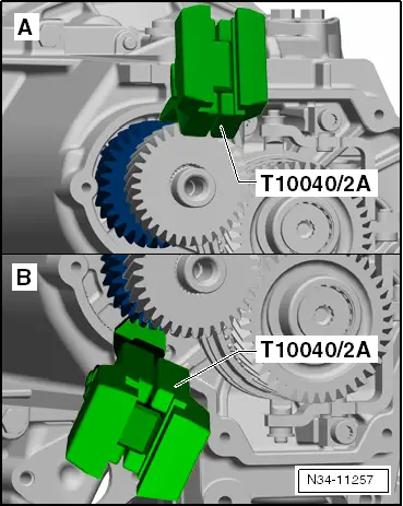
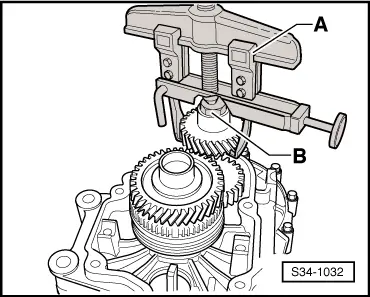
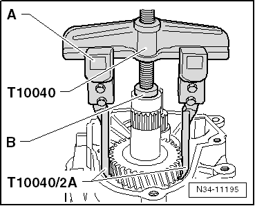
The extraction hooks -T10040/2A- cannot be correctly positioned.
-A-
the extraction hooks -T10040/2A- come prematurely in contact with:
t  the gearbox housing wall
t  the ribbing of the gearbox housing below the 5th gear pinion
Remove „together“: „5th/6th gear synchronizer body“, „6th gear pinion“, „5th gear pinion“ and „gearbox housing“ → Chapter
-B-
the extraction hooks -T10040/2A- come in contact with the ribbing in the gearbox housing below the 5th gear pinion.

   
The extraction hooks -T10040/2A- can be correctly positioned.
The 5th/6th gear can be removed separately → Anchor.

Remove 5th/6th gear separately
   
–  Remove shift fork and 5th/6th gear sliding sleeve as follows:
–  Cover the openings with a cloth.
–  Engage 5th gear -arrows 1- and -2-.
–  Remove 5th/6th gear shift gate -screw A-.
–  Then unscrew both screws -B- for bearing bolt.
–  Pull out bearing bolt.
–  Remove 5th/6th gear shift fork.
  S34-0982
–  Unscrew screws -A- for inner rings of the bearing on the input and output shaft, to this end engage the 5th gear -arrow°1- and the 1st °gear -arrow°2- and -arrow 3-.
–  The input and output shafts are blocked after enagaging both gears. Now it is possible to release the two bolts.
  Note
If the shafts are not replaced, carefully clean the threaded holes e.g. using a thread tap to remove locking agent residues.
  S34-0983
–  Remove 6th gear pinion with inner ring/cylindrical-roller bearing for output shaft.
A - Two-arm extractor, e.g. -Kukko 20/10-
B - Bolt M10 x 20
  Note
The 6th gear pinion with inner ring/cylindrical-roller bearing can also be removed using the two-arm extractor -T10040- and the extraction hooks -T10040/2A-.
–  If necessary, heat the gear pinion using the hot-air blower - V.A.G 1416-.
Separately remove the 6th gear pinion with inner ring/cylindrical-roller bearing for input shaft with the thrust washer as well as the 6th gear synchronizer ring or together with the 5th/6th gear synchronizer body with the inner ring for the 6th gear needle bearing as well as the 5th gear synchronizer ring.
  Note
t  As of production date 26.05.08, the corrugated spring ring is installed below the 5th gear synchronizer ring and above the 6th gear synchronizer ring.
t  Octavia II → Item and → Item.
t  Superb II → Item and → Item.
Use extractor - T10309-.
  S34-1032
–  First of all insert half of the bushing -T10309/1- between the output shaft -A- and the support of the 5th/6th gear shift fork -B-.
l  The shell -T10309/1- must be positioned below the synchronizer ring.
–  Turn the shell -T10309/1- to the opposite side -direction of arrow-.
  N34-10556
–  Insert the threaded insert -T10309/3- into the shell.
–  Now insert the second shell -T10309/1- and position the pipe -T10309/2- onto the device.
–  Check the synchronizer body for damage after removing.
–  Replace 5th gear synchronizer ring.
–  Remove sleeve from 5th gear pinion.
  N34-10555
–  Remove 5th gear pinion.
–  First of all insert the extraction hook-A-.
–  If necessary, heat the gear pinion using the hot-air blower - V.A.G 1416-.
-B-pressure plate -T10040/3 -
or
Thrust plate -MP3-467 (40 - 105)-
  Note
t  The 5th gear pinion can also be removed using the two-arm extractor -Kukko 20/10- in combination with the extraction hooks -T10040/2A-.
t  When pulling off the gear pinion make sure the hooks do not bend outwards. Check 5th gear for damage after removing.
  N34-11195

Installing 5th/6th gear and gearbox housing cover > < Mounting sequence - removing and installing gearbox housing cover and 5th/6th gear