
Octavia Mk2
 Note
Note
|

| 1 - | Clutch housing |
| 2 - | Outer ring/tapered-roller bearing |
| q | pressing off → Fig. |
| q | pressing on → Fig. |
| 3 - | Inner ring/tapered-roller bearing |
| q | pressing off → Fig. |
| q | pressing on → Fig. |
| 4 - | Drive shaft |
| q | adjust → Chapter |
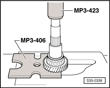
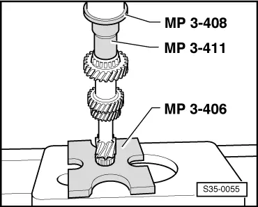
| 5 - | 3rd gear pinion |
| q | Collar points to the 4th gear |
| q | pressing off → Fig. |
| q | pressing on → Fig. |
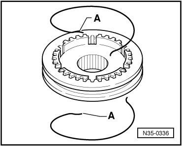
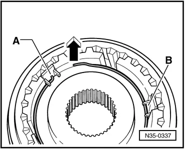
| 6 - | Circlip |
| q | always replace → Electronic Catalogue of Original Parts |
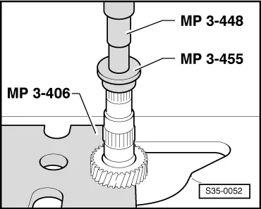
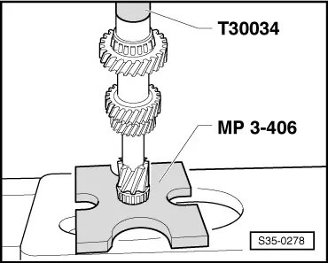
| 7 - | 4th gear pinion |
| q | pressing off with outer ring/tapered-roller bearing and bushing → Fig. |
| q | pressing on → Fig. |
| q | Collar points to the 3rd gear |
| 8 - | Inner ring/tapered-roller bearing |
| q | pressing off with 4th gear pinion and bushing → Fig. |
| q | pressing on → Fig. |
| 9 - | Thrust washer |
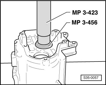
| 10 - | Outer ring/tapered-roller bearing |
| q | pressing off → Fig. |
| q | pressing on → Fig. |
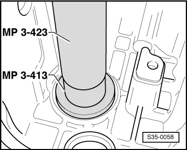
| 11 - | Adjusting washer |
| q | Determine thickness → Chapter |
| 12 - | Gearbox housing |
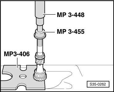
| 13 - | Bushing |
| q | for needle bearing |
| q | pressing off with 4th gear pinion and inner ring/tapered-roller bearing → Fig. |
| q | pressing on → Fig. |
| q | insert thrust washer Pos. 9 before assembly 9 |
| 14 - | Needle bearing |
| q | for 5th gear |
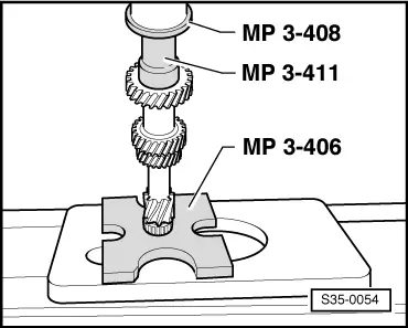
| 15 - | 5th gear sliding gear |
| q | remove together with 5th gear synchronizer body |
| 16 - | Corrugated spring ring |
| q | as of production date 26.05.08 |
| q | assign according to the → Electronic catalogue of original parts. |
| 17 - | 5th gear synchronizer ring |
| q | with integrated arresters Octavia II → Chapter |
| q | with integrated arresters Superb II → Chapter |
| q | check for wear Octavia II → Chapter |
| q | check for wear Superb II → Chapter |
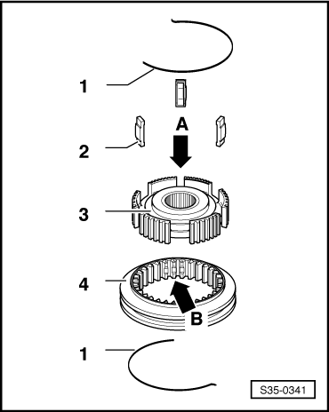
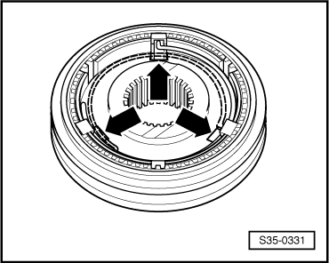
| 18 - | Sliding sleeve with 5th and 6th gear synchronizer body |
| q | Sliding sleeve was modified as of production date 06.06 → Fig. |
| q | removing and installing Octavia II → Chapter |
| q | removing and installing (Superb II) → Chapter |
| q | disassembling and assembling → Fig. |
| q | Setting 5th/6th gear (Octavia II up to production date 05.06) → Chapter |
| q | Setting 5th/6th gear (Octavia II as of production date 06.06) → Chapter |
| q | Setting 5th/6th gear (Superb II) → Chapter |
| q | Install springs bent at right angles and stops (on certain gearboxes) → Fig. |
| 19 - | 6th gear synchronizer ring |
| q | with integrated arresters Octavia II → Chapter |
| q | with integrated arresters Superb II → Chapter |
| q | check for wear Octavia II → Chapter |
| q | check for wear Superb II → Chapter |
| 20 - | Corrugated spring ring |
| q | as of production date 26.05.08 |
| q | assign according to the → Electronic catalogue of original parts. |
| 21 - | 6th gear sliding gear → Chapter |
| q | Octavia II → Chapter |
| q | Superb II → Chapter |
| 22 - | Needle bearing |
| q | for 6th gear |
| q | replace together with bushing |
| q | Octavia II → Chapter |
| q | Superb II → Chapter |
| 23 - | Bushing |
| q | for 6th gear needle bearing |
| q | replace together with needle bushing |
| q | Octavia II → Chapter |
| q | Superb II → Chapter |
| 24 - | Thrust washer (Octavia II) → Chapter |
| q | no longer available as of production date 09.06 |
| 25 - | Inner ring for cylindrical-roller bearing (Octavia II up to 08.06) → Chapter |
| q | for drive shaft |
| q | identify before removing |
| q | do not interchange with inner ring/cylindrical-roller bearing of output shaft |
| 26 - | Inner ring/cylindrical-roller bearing (as of 09.06) |
| q | for drive shaft |
| q | Superb II → Chapter |
| q | Octavia II → Chapter |
| q | Octavia II - Guide inner ring/cylindrical-roller bearing Pos. 25 together with thrust washer Pos. 24 → Fig. |
| 27 - | Screw with internal serrations |
| q | for drive shaft |
| q | Octavia II → Chapter |
| q | Superb II → Chapter |
| q | up to production date 08.06: 40 Nm + torque a further 180° |
| q | as of production date 09.06: 80 Nm + torque a further 90° |
| q | self-locking |
| q | always replace → Electronic Catalogue of Original Parts |
|
|
|
|
|
|
|
|
|
|
|
|
|
|
|
|
|
|
|
|
|
|
|
|
|
|
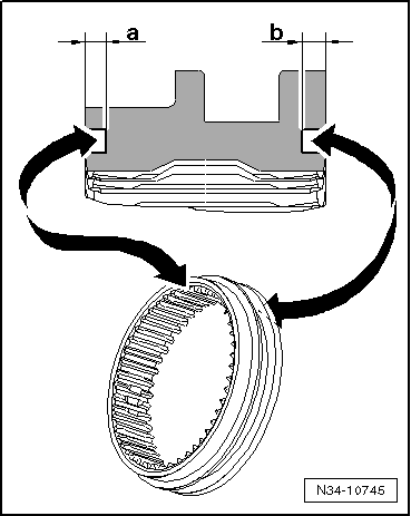
| Dimension -a- (side to 6th gear) | |
| »Gearbox up to production date 05.06« | »Gearbox as of production date 06.06« |
| 1.5 mm | 1.8 mm |
| Assign sliding sleeve and 5th/6th gear synchronizer body via the → Electronic Catalogue of Original Parts. |
| Dimension -b- (side to 5th gear) | |
| »Gearbox up to production date 05.06« | »Gearbox as of production date 06.06« |
| 1.5 mm | 2.0 mm |
| Assign sliding sleeve and 5th/6th gear synchronizer body via the → Electronic Catalogue of Original Parts. |
|
Note
|
|
|
|
|
|
|
|