skoda Workshop Repair Guides

Skoda Workshop Service and Repair Manuals

Clutch, control > < General repair information
Components
Components
Gearbox
t  Thoroughly clean the connection points and their surroundings before releasing.
t  Bolts and other attachments should have a classification in the → Electronic Catalogue of Original Parts.
t  When installing the manual gearbox, ensure the dowel sleeves are correctly located between the engine and gearbox.
t  When installing mounts as well as waxed components, the contact surfaces must be cleaned. Contact surfaces must be free of wax and grease.
t  When replacing the gearbox, inspect the gearbox oil level and top up with oil if necessary → Chapter.
t  Filling capacity and specification (Octavia II) → Chapter.
t  Filling capacity and specification (Superb II) → Chapter.
Vehicles Octavia ll with four-wheel drive
Angle gearbox (four-wheel drive)
t  The angle gearbox is screwed on laterally to the manual gearbox and has its own closed oil circulation system.
t  Filling capacity → Chapter.
t  Oil specification → Chapter.
t  Inspect gear oil level (top up oil if necessary) → Chapter.
Rear final drive
t  If the rear final drive is replaced, inspect the gear oil level (top up oil if necessary) → Chapter as well as the oil level in the Haldex coupling (top up oil if necessary) → Chapter.
t  Filling capacity → Chapter.
t  Oil specification → Chapter.
t  When installing carriers as well as waxed components, the contact surfaces must be cleaned. Contact surfaces must be free of wax and grease.
  Note
t  The „Haldex coupling“ is installed in the rear final drive.
t  The final drive and the „Haldex coupling“ have separate oil circulation systems.
t  The final drives „02D/0AV“ are fitted with the „Haldex coupling of the 2nd generation“.
t  The final drive „OBR“ is fitted with the „Haldex coupling of the 4th generation“.
t  The rear final drives „02D/0AV“ and „OBR“ have different „Haldex couplings“.
t  Oil for Haldex coupling, assignment via the → Electronic Catalogue of Original Parts.
Targeted fault finding, Vehicle self-diagnosis and Measuring method
t  Before repairing the Haldex coupling try to determine the cause of the fault as accurately as possible using → Vehicle diagnostic, testing and information system VAS 5051 in the functions „Targeted fault finding“, „Vehicle self-diagnosis“ and „Measuring method“.
Continued for all vehicles
Sealant
t  Thoroughly clean the contact surfaces of the housing before applying the silicone sealant.
t  Apply sealant AMV 188 200 03 evenly and not too thick.
O-rings, gasket rings, gaskets
t  Always replace O-rings, gasket rings and gaskets → Electronic Catalogue of Original Parts.
t  After removing gaskets, check the contact surface in the housing or shaft for burrs or damage which occured during the assembly.
   
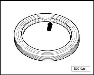
t  Radial shaft seals - before mounting lightly oil at outside diameter and fill half the space between the sealing lips -arrow- with sealing grease G 052 128 A1.
t  The open side of the sealing rings is turned towards the fluid to be sealed.
t  Press in new gasket ring in such a way that the sealing lip is not located on the same point as the sealing lip of the old gasket ring (use tolerance for insertion depth).
t  Before inserting lightly oil the O-rings, in order to prevent the rings being squashed during installation.
t  Inspect the oil level after replacing the gaskets and gasket rings → Chapter.
Circlips
t  Do not over-tension the circlips.
t  Always replace damaged or tensioned circlips → Electronic Catalogue of Original Parts.
t  Circlips must be positioned in the base of the groove.
  S00-0264
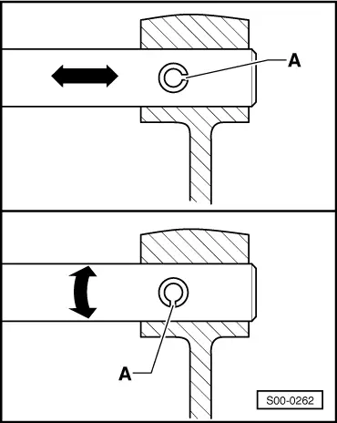
t  Replace roll pins. Fitting position: Slot -A- longitudinal to power flow -arrow-.
Screws, nuts
t  Slacken the bolts and nuts against the tightening sequence.
t  Slacken and tighten screws or fixing nuts of covers and housings without tightening sequence diagonally across in stages.
t  Replace the self-locking screws and nuts.
t  Tightening torques apply for non-oiled nuts and bolts.
t  Clean all threaded holes into which self-locking screws or screws with locking agent are inserted (using e.g. a thread tap). Otherwise there is a risk that the bolts will shear at the next disassembling.
t  It is important to ensure at all bolted connections that the contact surfaces as well as the nuts and bolts are waxed only after being installed, should this be necessary.
Bearings
t  New taper roller bearings are fitted as supplied and do not require any additional lubrication.
t  Insert moist all bearings (except taper roller bearings) in the gearbox with gear oil.
t  Heat the inner rings/tapered-roller bearings on a heating plate or with the induction heater unit e.g. -VAS 6414- to approx. 100°C for installing. Install axial and play-free up to the stop.
t  Do not mix up the outer and inner races of bearings of the same size.
t  Always jointly replace tapered-roller bearings on the same shaft and use products of the same manufacturer.
t  Position needle bearing with the lettered side (thicker end) towards the drift pin.
Shims
  S00-0262
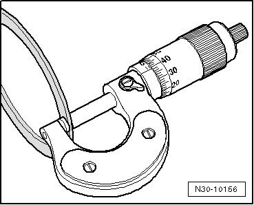
t  Gauge shims at several points with a micrometer. Different tolerances allow to measure the required thickness for each washer very precisely.
t  Inspect for burrs and damage. Install only adjusting washers which are in perfect condition.
Synchronizer rings
t  Do not interchange the synchronizer rings, if re-used assign to the same gear.
t  Inspect for wear, replace if necessary → Electronic Catalogue of Original Parts.
  N30-10156
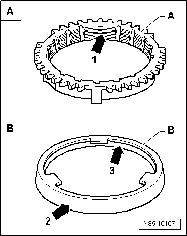
t  Check grooves -arrow 1- on synchronizer ring -A-, or check the inside of the ring for flattened parts (grooves worn).
t  When installing the intermediate ring -B-, check outer contact surface -arrow 2- and inner contact surface -arrow 3- for grooves, blue coloring (caused by overheating) and other damages.
t  Insert with some gearbox fluid.
Pinions
t  Clean and heat with induction heater unit e.g. -VAS 6414- to approx. 100°C before pressing on.
t  The temperature can be checked with a temperature measuring instrument.
t  Check fitting position.
Sliding gears
t  Inspect wheels 1st to 6th gear for small axial play or clearance after installation.
Damage to sliding gears or sliding sleeves
  N35-10107
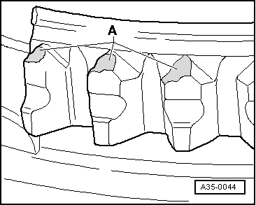
t  Damage to synchronizer ring or sliding gear
A - Worn tooth pointing of the clutch gearing (engaging gearing) to synchronizer ring or sliding gear.
  A35-0044
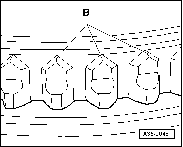
t  To compare: Synchronizer ring or sliding gear undamaged
B - Undamaged tooth pointing of the clutch gearing (engaging gearing) to synchronizer ring or sliding gear.
  A35-0046
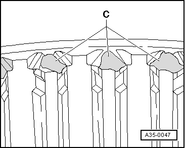
t  Damage to the sliding sleeve:
C - Worn tooth pointing of the longitudinal internal serration to the sliding sleeve.
  A35-0047
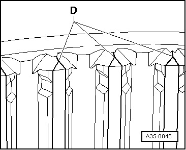
t  To compare: Sliding sleeve undamaged
D - Undamaged tooth pointing of the longitudinal internal serration to the sliding sleeve.
Clutch control
t  When removing gearbox, remove slave cylinder, do not detach the hoses.
t  If the slave cylinder with connected hydraulic line is removed, do not depress the clutch pedal. Otherwise the tappet is pressed out of the slave cylinder.
t  Do not tilt the clutch pressure plate; release and tighten crosswise in small stages.
t  If the clutch pedal does not return to its initial position after the coupling procedure - clutch pedal in home position - the clutch control must be bled (further measures Octavia II → Chapter, Superb II → Chapter).
t  In order to reduce unpleasant odours if the clutch is burnt, thoroughly clean the clutch bell as well as the flywheel and the engine on the side of the gearbox.
  A35-0045

Clutch, control > < General repair information