
Octavia Mk2
 Note
Note| t | Before installing, heat the inner ring/tapered-roller bearing with the hot-air blower -V.A.G 1416- to 100°C. |
| t | Replace both tapered-roller bearings together. |
| t | When replacing the tapered-roller bearings, the differential housing, the gearbox housing or the clutch housing, set the differential gear → Chapter. |

| 1 - | Conical screw, 25 Nm |
| q | screw into threaded piece Pos. 8 |
| 2 - | Right flange shaft |
| 3 - | Pressure spring for flange shaft |
| q | fitted behind flange shafts |
| 4 - | Thrust washer |
| q | Fitting position: Collar towards pressure spring |
| 5 - | Conical ring |
| q | Fitting position: Cone towards differential gear housing |
| 6 - | Circlip |
| q | holds the conical ring, stop disc and pressure spring in position when the flange shaft is removed |
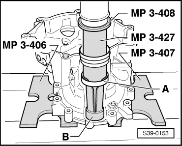
| 7 - | Large differential bevel gear |
| q | installing → Fig. |
| 8 - | Threaded part |
| q | installing → Fig. |
| 9 - | Differential bevel gear shaft |
| q | when removing, the tensioning sleeve Pos. 18 is cut out → Fig. |
| q | installing → Fig. |
| 10 - | Small differential bevel gear |
| q | installing → Fig. |
| 11 - | Stop disc compound |
| q | when installing moisten with gearbox oil |
| 12 - | Flange shaft left |
| 13 - | Seal ring for left flange shaft |
| q | replace with installed gearbox → Chapter |
| 14 - | Adjusting washer S1 |
| q | for differential gear |
| q | always 1 mm thick |
| q | on gearboxes as of production date 12.06 the adjusting washer S1 for outer ring/tapered-roller bearing is not fitted → Chapter |
| q | Bearing pedestal for outer ring/tapered-roller bearing is adapted |
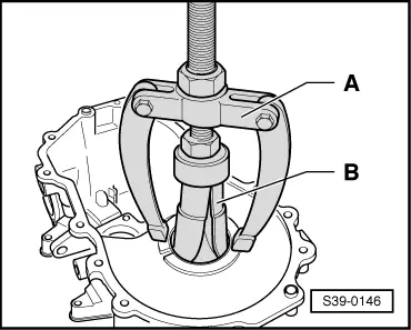
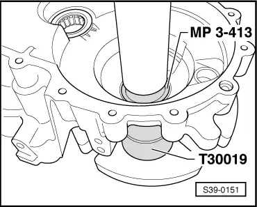
| 15 - | Outer ring/tapered-roller bearing |
| q | removing → Fig. |
| q | installing → Fig. |
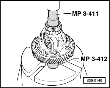
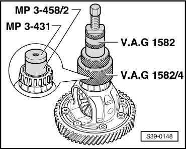
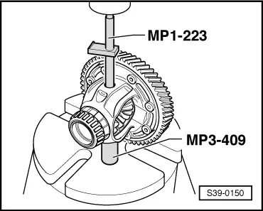
| 16 - | Inner ring/tapered-roller bearing |
| q | remove → Fig. |
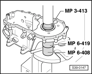
| q | pressing on → Fig. |
| 17 - | Differential gear housing |
| q | with gear pinion for final drive |
| 18 - | Tensioning sleeve |
| q | to secure the differential bevel gear shaft |
| q | is cut when removing → Fig. |
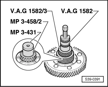
| 19 - | Inner ring/tapered-roller bearing |
| q | remove → Fig. |
| q | pressing on → Fig. |
| 20 - | Outer ring/tapered-roller bearing |
| q | pressing out → Fig. |
| q | installing → Fig. |
| 21 - | Adjusting washer S2 |
| q | for differential gear |
| q | Determine thickness → Chapter |
| 22 - | Seal ring for right flange shaft |
| q | replace with installed gearbox → Chapter |
| 23 - | Gearbox housing |
| q | repairing → Chapter |
| q | on gearboxes as of production date 12.06 the adjusting washer S1 for outer ring/tapered-roller bearing is not fitted → Chapter |
| q | Bearing pedestal for outer ring/tapered-roller bearing is adapted |
| 24 - | Clutch housing |
| q | repairing → Chapter |
|
|
|
|
Note
|
|
|
|
 WARNING
|
|
|
|
|
|
|
|
|
|
|
|