Octavia Mk2
| Summary of components - Control cables up to 10.06 |
 Note
Note| Grease bearing and friction surfaces with grease -G 000 450 02-. |

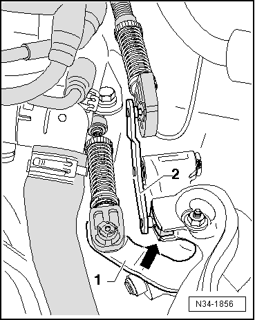
| 1 - | Shift cable |
| q | connect with cable lock Pos. 11 |
| q | Fitting position → Chapter |
| q | removing and installing → Chapter |
| q | adjust → Chapter |
| q | as of 11.06 the attachment of the control cable in the shift housing is modified → Chapter |
| 2 - | Selector cable |
| q | connect with cable lock Pos. 10 |
| q | Fitting position → Chapter |
| q | removing and installing → Chapter |
| q | adjust → Chapter |
| q | as of 11.06 the attachment of the control cable in the shift housing is modified → Chapter |
| 3 - | Lock washer |
| q | always replace → Electronic Catalogue of Original Parts |
| q | as of 11.06 the lock washers are no longer available → Chapter |
| 4 - | Shift housing |
| 5 - | Lock washer |
| q | do not damage cables when removing |
| q | always replace → Electronic Catalogue of Original Parts |
| 6 - | 20 Nm |
| q | 3 pieces |
| q | for cable support |
| 7 - | Cable support |
| q | made out of plastic or metal |
| 8 - | Grommet |
| q | for mounting of cable support to gearbox |
| 9 - | Spacer |
| 10 - | Cable lock |
| q | for selector cable at relay lever |
| q | do not interchange, cable locks for selector cable at relay lever and for shift cable at gearshift lever are different → Fig. |
| q | after installing set shift mechanism → Chapter |
| q | as of 06.07 it is fitted together with plastic relay lever → Chapter |
| q | remove from plastic relay lever → Chapter |
| q | press onto plastic relay lever → Chapter |
| q | Assignment → Fig. |
| 11 - | Cable lock |
| q | for shift cable at gearbox shift lever |
| q | do not interchange, cable locks for selector cable at relay lever and for shift cable at gearshift lever are different → Fig. |
| q | after installing set shift mechanism → Chapter |
| 12 - | Lock washer |
| q | always replace → Electronic Catalogue of Original Parts |
| q | is not required for cable lock for selector cable at relay lever, if relay lever is made of plastic |
| 13 - | Lock washer |
| q | always replace → Electronic Catalogue of Original Parts |
| q | is not required, if the relay lever is made of plastic |
| 14 - | Bushing |
| q | is not required, if the relay lever is made of plastic |
| 15 - | Reversing lever |
| q | Fitting position → Fig. |
| q | after installing set shift mechanism → Chapter |
| q | as of 06.07 the relay level is made of plastic |
| q | Removing and installing plastic relay lever together with cable lock → Chapter |
| q | If the relay lever is made of plastic, neither the bushings pos. 14 nor the lock washer pos. 12 are required |
| 16 - | Sliding shoe |
| 17 - | 23 Nm |
| q | always replace → Electronic Catalogue of Original Parts |
| 18 - | Gearshift lever |
| q | with balancing weight |
| q | insert in such a way that the interrupted spacing of the teeth matches the gearshift shaft |
| q | Fitting position → Fig. |
| q | after installing set shift mechanism → Chapter |
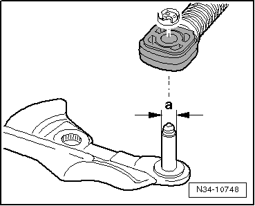
| q | as of 06.06 the diameter of the fixing bolt is smaller → Fig. |
|
|
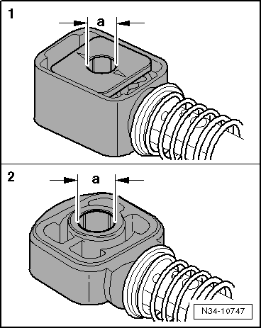
| Cable lock: | Dimension „a“ |
| 1 - as of 06.06 - Shift cable at gearbox shift lever | 8.5 mm |
| 2 - until 05.06 - Shift cable at gearbox shift lever | 10 mm |
| 2 - Selector cable at relay lever | 8 mm |
| 2 - Selector cable at plastic relay lever → Chapter | 10 mm |
|
|
| Fixing bolts: | Dimension „a“ |
| until 05.06 - Shift cable at gearbox shift lever | 10 mm |
| as of 06.06 - Shift cable at gearbox shift lever | 8.5 mm |