skoda Workshop Repair Guides

Skoda Workshop Service and Repair Manuals

Clutch, control > < Designation of components and transmission ratio
General repair information
Scrupulous care and cleanliness as well as the proper tools are essential requirements for carrying out proper and successful gearbox repairs. Obviously, the generally valid basic safety rules apply to repair work.
A number of generally valid notes for individual repair operations - which are otherwise listed several times at numerous points in the workshop manual - are summarized here. They apply to this workshop manual.
Gearbox
Gearboxes are constructed of aluminium and of magnesium → Chapter.
t  Gearbox housing and clutch housing are made of the same materials.
t  Bolts and other attachments that come into direct contact with the gearbox can have varying finishes depending on whether the gearbox is made of aluminium or magnesium.
t  On magnesium gearboxes, the screws must always be replaced at the following screw connections: Gearbox housing cover to gearbox housing and clutch housing to gearbox housing.
t  The use of substitute components causes contact corrosion. This will result in damage to the gearbox.
t  Bolts and other attachments should have a classification in the → Electronic Catalogue of Original Parts.
t  When installing, ensure the dowel sleeves are correctly located between the engine and gearbox.
t  When replacing the gearbox, pour in gear oil up to lower edge of filler hole → Chapter.
t  Capacities and specifications → Chapter.
Gaskets, seals
t  Thoroughly clean contact surfaces and apply sealant AMV 188 200 03.
t  Apply sealant evenly - not too thickly.
t  Replace O-rings → Electronic Catalogue of Original Parts.
t  Replace radial shaft seals.
Before installing:
   
Lightly oil the outer diameter. Fill half the space between the sealing lips -arrow- with grease -G 052 128 A1-.
After installing:
Check gear oil level, if necessary pour in up to lower edge of filler hole → Chapter, specification → Chapter.
Locking elements
t  Replace circlips.
t  Do not over-tension the circlips.
t  Circlips must be positioned in the base of the groove.
  N32-0001
t  Replace roll pins. Fitting position: Slot longitudinally to power flow -arrow-.
  V34-1515
Screws, nuts
t  Slacken and tighten nuts and bolts for attaching covers and housings diagonally across in stages.
t  Do not twist particularly sensitive parts - e.g. clutch pressure plates - and slacken and tighten diagonally across in stages.
t  Tightening torques apply for non-oiled nuts and bolts.
t  Always replace the self-locking screws and nuts → Electronic Catalogue of Original Parts.
t  It is important to ensure at all bolted connections that the contact surfaces as well as the nuts and bolts are waxed only after being installed, should this be necessary.
t  Clean all threaded holes into which self-locking bolts were screwed in, using a suitable thread tap to remove old locking agent residues. Otherwise there is the risk that the self-locking screw will shear when removing.
Bearings
t  New taper roller bearings are fitted as supplied and do not require any additional lubrication.
t  Fit needle bearings to the gearbox with some gearbox fluid.
t  Replace all taper roller bearings belonging to one shaft at the same time. As far as possible use bearings of the same make.
t  Before installing, heat the inner races of the bearings on a heating plate or with the hot-air blower -V.A.G 1416- to approx. 100°C, when installing press in axial and play-free up to the stop.
t  The temperature can be checked with a temperature measuring instrument.
t  Do not exchange the outer and inner rings of bearings of the same size - bearings go in pairs.
t  Position needle bearing with the lettered side (thicker end) towards the drift pin.
Shims
  N00-0383
t  Gauge shims at several points with a micrometer. Different tolerances allow to measure the required thickness for each washer very precisely → electronic catalogue of original parts.
t  Inspect washers for burrs and damage.
t  Install only adjusting washers which are in perfect condition.
Synchronizer rings
t  These are not interchangeable. If re-using, allocate synchronizer rings to the same sliding gear.
t  Inspect for wear, replace if necessary → Electronic Catalogue of Original Parts.
  N30-10156
t  
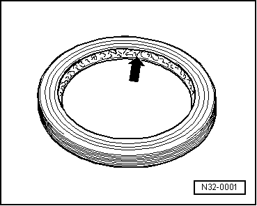
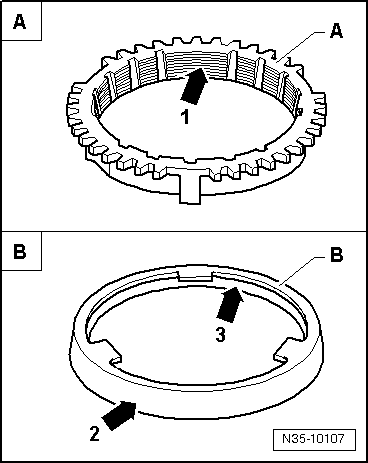
Check grooves -arrow 1- on synchronizer ring -A-, or check the inside of the ring for flattened parts (grooves worn).
t  When installing the intermediate ring -B-, check outer contact surface -arrow 2- and inner contact surface -arrow 3- for grooves, blue coloring (caused by overheating) and other damages.
t  Insert with some gearbox fluid.
Pinions
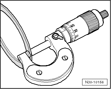
Clean and heat on a heating plate or with the hot-air blower -V.A.G 1416- to approx. 100°C before pressing on.
The temperature can be checked with a temperature measuring instrument.
Check fitting position.
Clutch control
t  When removing gearbox, remove slave cylinder, do not detach the hoses.
t  If the slave cylinder with connected hydraulic line is removed, do not depress the clutch pedal. Otherwise the tappet is pressed out of the slave cylinder.
t  Do not tilt the clutch pressure plate; release and tighten crosswise in small stages.
t  If the clutch pedal does not return to its initial position after the coupling procedure - clutch pedal in home position - the clutch control must be bled (further measures → Chapter).
t  In order to reduce unpleasant odours if the clutch is burnt, thoroughly clean the clutch housing as well as the flywheel and the engine on the side of the gearbox.
  N35-10107

Clutch, control > < Designation of components and transmission ratio