
Octavia Mk2
 Note
Note
|
|
|
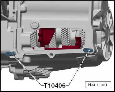
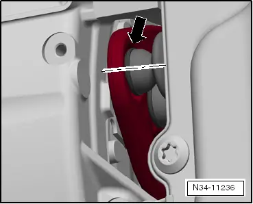
Note| t | Make sure that all the shift forks are in the »centre position« before installing the mechatronics for double clutch gearbox -J743-. |
| t | The »centre position« is shown in the illustration as position -N- (neutral). |
| t | No gear is engaged in this position, i.e neutral (neutral position) is engaged. |
| – | First check all 4 shift forks by hand. |
| All shift forks have 3 positions: |
| t | Gear engaged |
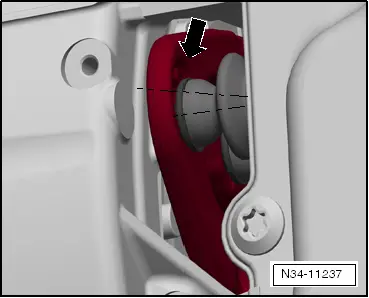
| t | Neutral -N- |
| t | Gear engaged |
| – | Consecutively bring all 4 shift forks once into each position -arrows-, if necessary turn a little on the pinions. |
| – | Then bring all the shift forks again into the »centre position«, position -N-. |

| N - | Neutral |
| R - | Reverse gear |
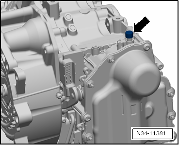
Note| t | When the reverse gear is engaged, the extended tappet of the mechatronics is hooked on the gearbox housing. |
| t | Therefore, the mechatronics must be put into the removal position by hand → Chapter. |
| 1 - | first gear |
| 2 - | second gear |
| 3 - | third gear |
| 4 - | fourth gear |
| 5 - | fifth gear |
| 6 - | sixth gear |
| 7 - | seventh gear |
|
|
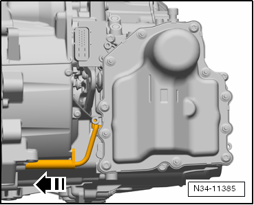
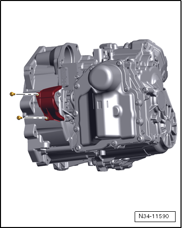
| Adjust gear actuator: |
 Caution
|

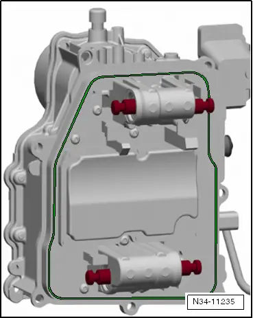
| – | Set the 4 gear switches on the rear side of the mechatronics for double clutch gearbox -J743- into the specified position. |
| Specified position: -a- = 25 mm |
Note
|
|
|
|
|
Note |
|
|
|
|
|
|
|
Note
|
|
|
|
|
|