skoda Workshop Repair Guides

Skoda Workshop Service and Repair Manuals

Place the mechatronics for double clutch gearboxJ743 by hand in the »removal position« > < Removing mechatronics for double clutch gearboxJ743; gearbox removed (Octavia II, Superb II, Yeti)
Removing mechatronics for double clutch gearboxJ743; gearbox installed (Octavia II, Superb II, Yeti)
Removing mechatronics for double clutch gearbox -J743-; gearbox installed (Octavia II, Superb II, Yeti)
Special tools and workshop equipment required
t  Assembly lever -T10407-
t  Vehicle diagnosis, measurement and information system -VAS-
t  Catch pan for workshop crane -VAS 6208-
  Note
t  Observe safety instruction for the mechatronics for double clutch gearbox -J743- → Chapter.
t  Observe instructions for automatic gearbox DSG - 0AM → Chapter.
t  General repair information → Chapter.
t  The clutch is self-adjusting. Vibrations can have a negative effect on the adjusting device. Also when the mechatronics is removed, the »sudden removal« of the drifts below the engaging levers can have a negative effect on the adjusting device.
t  
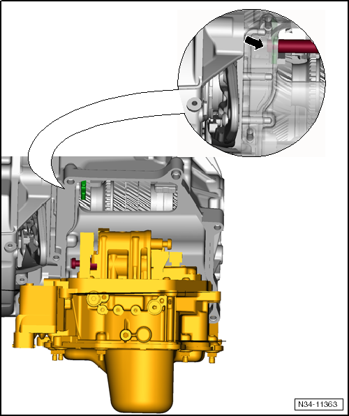
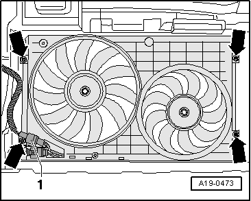
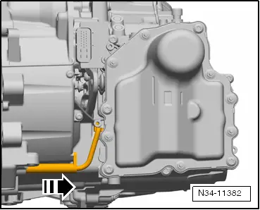
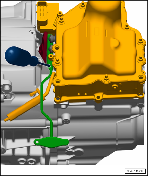
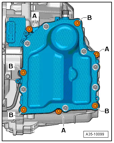
Ensure adequate clearance in front of the gearbox in order to remove the mechatronics. Components, which are not directly connected with the gearbox, must be removed on some vehicles. The existing brackets, if applicable, must be removed at the screws of the cover for mechatronics.
t  After the battery earth strap is disconnected and connected, carry out additional operations → Electrical System; Rep. gr.27.
The mechatronics remains filled with oil
–  Shift selector lever into position »P«.
Before the actual removal of the mechatronics, carry out the basic setting of the »idle position« of the gearbox with the → Vehicle diagnostic tester.
–  Select Targeted functions and subsequently select the basic setting of the idle position.
–  Disconnect the battery-earth strap with the ignition off → Electrical System; Rep. gr.27.
–  Remove air filter → Engine; Rep. gr.24 or → Engine; Rep. gr.23.
–  Remove battery and battery tray → Electrical System; Rep. gr.27.
   
–  Unlock the cap for the plug of the mechatronics by pulling in -direction of arrow- and disconnect the plug.
  N34-11386
–  Remove the cover from the ventilation and close with a suitable screw plug so that no oil can flow out.
  WARNING
Hot steam may escape after the compensation bottle is opened. Cover the cap with a cloth and open carefully.
–  When the engine is warm the cooling system is under pressure. Slowly open the cap of the compensation bottle, in order to first reduce pressure before pulling off the coolant hoses.
–  Remove the sound dampening system → Body Work; Rep. gr.50.
–  Remove the charge air hose from the bottom left charge air cooler and the charge air pipe → Engine; Rep. gr.21.
  Note
Shut off the opening of the charge air cooler so that no coolant can penetrate.
  N34-11381
–  Disconnect plug -2- at the coolant temperature sender at radiator outlet -G83-.
–  Place a catch pan for workshop crane -VAS 6208- under the radiator.
–  Remove the bottom coolant hose -1- from the radiator, to do so raise the retaining clip → Engine; Rep. gr.19.
  A19-10607
–  Separate the plug connections -1- of the bottom radiator fan at the fan shroud.
–  Screw out screws -arrows- and remove fan shroud with radiator fans downwards.
–  Remove the electrical lines from the front holder at the mechatronics and tie up to the top.
–  Remove the holder from the mechatronics.
–  Position the catch pan under the gearbox.
  A19-0473
–  Release oil drain plug -arrow- at the gearbox.
  A34-10532
–  Drain off oil.
–  Install oil drain plug.
  N34-11371
–  Remove all the brackets from the gearbox.
  N34-10966
–  Carefully unlock the gearbox input r.p.m. sender -G182- with a screwdriver and pull it out of the housing in the -direction of arrow-.
  N34-11382
Now both levers of the clutch control must be pressed off the mechatronics with the assembly lever -T10407-. Otherwise the lever for mechatronics strikes the tappets and the mechatronics cannot be removed.
  N34-11217
–  Insert the assembly lever -T10407- as a safety between both clutch control levers and gearbox housing.
  N34-11218
The assembly lever -T10407- should rest with the complete surface of the »reverse side« against the gearbox housing and the nut should form one level with the recess of the housing.
  Note
The recess of the housing and the nut on the lever must form one level. Do not insert the assembly lever -T10407- up to the stop.
  N34-11219
–  Turn the assembly lever -T10407- to the left in -direction of arrow- and thus press the engaging lever away from the tappets.
  Note
Do not remove the assembly lever -T10407-.
  N34-11232
If necessary, press the assembly lever -T10407- against the gearbox using a screwdriver, thereby both levers of the clutch control are pressed off the mechatronics.
  Note
While doing so, the rubber grommets of the clutch actuators should not be damaged.
  N34-11220
–  Release long screws -B- (4 pieces, M8 x 90) crosswise.
  A35-10099
–  Release the remaining screws -A- (3 pieces, M8 x 35) crosswise.
  Note
t  Do not remove more than 7 screws! »There are 4 long and 3 short screws«.
t  Do not slacken the cover screws of the mechatronics.
t  Place down the removed mechatronics in such a way that no oil can flow out of the ventilation.
t  Drained oil must not be refilled.
–  Grab with the hand (without gloves) at the mass, in order to discharge yourself electrostatically.
  Caution
t  Only then touch or remove the mechatronics for double clutch gearbox -J743-, after you have discharged yourself electrostatically at an earthed object beforehand, e.g. skin contact with mass.
t  Under no circumstances must the plug contacts in the plug of the gearbox be touched with the hands, because the control unit can be destroyed through static discharge as well as the mechatronics.
–  Remove mechatronics.
  Note
The »removed«mechatronics is sent back with oil (close the ventilation opening with a suitable plug).
  A35-10099
If the mechatronics »clamps«:
It is possible that the mechatronics cannot be removed. In this case, the gear actuator »jams« at the »top left« on the gearbox housing.
In this case, the mechatronics should not be removed with increased force.
–  In this case, the mechatronics must be put into the »removal position« by hand → Chapter.
Install mechatronics on installed gearbox → Chapter.
  N34-11363

Place the mechatronics for double clutch gearboxJ743 by hand in the »removal position« > < Removing mechatronics for double clutch gearboxJ743; gearbox removed (Octavia II, Superb II, Yeti)