skoda Workshop Repair Guides

Skoda Workshop Service and Repair Manuals

Assembly bracket > < Securing the engine to the assembly stand
Installing the engine
(Octavia II, Superb II, Yeti)
Special tools and workshop equipment required
t  Grease -G 000 100- for manual gearbox
t  
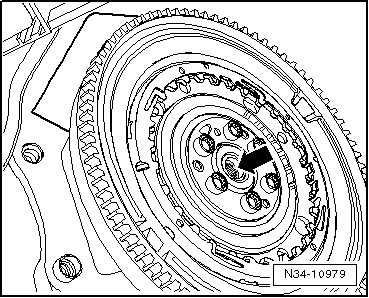
High temperature grease -G 052 133 A2- for automatic gearbox
Precondition
l  Fit engine and gearbox using engine mount to the engine/gearbox jack.
Installation is performed in the reverse order, pay attention to the following points:
  Note
t  Observe all safety measures and notes for assembly work on the fuel supply and injection system, at the charge air system and observe as well the rules for cleanliness → Chapter.
t  Always replace self-locking nuts.
t  Replace screws which have been tightened to a torquing angle.
t  Always replace gasket rings and seals.
t  All cable straps should be fastened again in the same place when installing.
t  Secure all hose connections with corresponding hose clamps → Electronic Catalogue of Original Parts.
  Caution
When undertaking all installation work, particularly in the engine compartment because of its cramped construction, please observe the following:
t  Lay lines of all kinds (e.g. for fuel, hydraulic fluid, cooling fluid and refrigerant, brake fluid, vacuum) and electrical lines in such a way that the original line guide is re-established.
t  In order to avoid damage to the cables, ensure that there is adequate free access to all moving or hot components.
For vehicles with manual gearbox
  Note
t  Clean the serration of the drive shaft and if the clutch disc has been used clean the hub serration, remove corrosion and only apply a very thin layer of grease -G 000 100- on the serration. Subsequently move the clutch disc up and down on the drive shaft until the hub fits smoothly on the shaft. Always remove excess grease.
t  After installing the coupling, check the centering of the clutch disc → Gearbox; Rep. gr.30.
t  Check the clutch release bearing for wear. Replace release bearing if worn → Gearbox; Rep. gr.30.
For vehicles with automatic gearbox DSG
   
–  Replace the needle bearing -arrow- in the crankshaft → Chapter.
  Note
Lubricate needle bearing and drive shaft pin with a thin layer of high temperature grease -G 052 133 A2-. Do not grease the serration of the drive shaft.
Continued for all vehicles
–  Check whether the dowel sleeves for centering the engine/gearbox are present in the cylinder block; insert if necessary.
  N34-10979
–  Ensure that the intermediate plate has been inserted on the sealing flange and is pushed onto the dowel sleeves -arrows-.
–  Screw on gearbox to engine → Gearbox; Rep. gr.34.
–  Insert engine with gearbox into the body.
  S13-0541
–  Successively screw in by hand the screws for engine mount -arrows-.
For the vehicles Octavia II
  S10-0267
–  Successively screw in by hand the screws for gearbox mount -arrows- at gearbox 0A4 -arrows- or ...
  S10-0268
–  ... at gearbox 02Q -arrows- or ...
  S34-0875
–  ... at gearbox 0AM -2-.
For the vehicles Superb II, Yeti
  N34-10976
–  Successively screw in by hand the screws for gearbox mount -arrows-.
For all vehicles
–  Align engine and gearbox mount and tighten screws:
t  Octavia II, Yeti → Chapter.
t  Superb II → Chapter.
–  Remove engine mount -T10012- from engine.
–  Install pre-exhaust pipe with diesel particle filter → Chapter.
  S10-0268
–  First tighten pendulum support with new screws -2- and -3- at gearbox and then tighten with new screw -1- at assembly carrier.
–  Install the left as well as the right drive shaft → Chassis; Rep. gr.40.
For vehicles with manual gearbox
–  Connect hydraulic line to breather/clutch slave cylinder and bleed the clutch hydraulic → Gearbox; Rep. gr.30.
–  Attach shift mechanism to gearbox and adjust → Gearbox; Rep. gr.34.
For models with automatic gearbox
–  Attach the shift mechanism to the gearbox → Automatic Gearbox; Rep. gr.34.
Continued for all vehicles
–  Install AC compressor at the bracket for auxiliary units → Chapter.
–  Install the V-ribbed belt → Chapter.
–  Install radiator → Chapter.
–  Install fan shroud with radiator fans → Chapter, to do so ensure adequate clearance of the blower motors.
–  Connect all connecting, fuel, cooling fluid, vacuum and suction hoses to the engine.
–  Connect electrical connections and attach cables → Current flow diagrams, Electrical fault finding and Fitting locations.
–  Carry out cohesive work when reconnecting the battery → Electrical System; Rep. gr.27.
–  Install bulkhead plenum chamber and plenum chamber cover → Body Work; Rep. gr.66.
–  Install wiper arms → Electrical System; Rep. gr.92.
–  Top up coolant → Chapter.
–  Checking the oil level:
t  → BookletOctavia II.
t  → BookletSuperb II.
t  → BookletYeti.
–  Install the bottom part of the right and left wheelhouse liner → Body Work; Rep. gr.66.
–  Install the noise insulation → Body Work; Rep. gr.50.
–  Filling and bleeding the fuel system. For this purpose, connect the vehicle diagnosis, measurement and information system -VAS 505x- and carry out the targeted function „bleeding the fuel system“. During this function, the fuel pump is actuated for 180 seconds.
–  Check fuel system for tightness → Chapter.
–  Perform a test drive.
–  Interrogate all fault memories, if necessary rectify any faults existing and erase the fault memory → Vehicle diagnostic tester.
  Note
After deleting the fault memory of the engine control unit the readiness code must be re-generated.
Tightening torques
  S10-0269
ComponentNm
Screws or nutsM610
 M715
 M820
 M1040
 M1270
Engine/gearbox connecting screws → Gearbox; Rep. gr.34 


Assembly bracket > < Securing the engine to the assembly stand