
Octavia Mk2
|
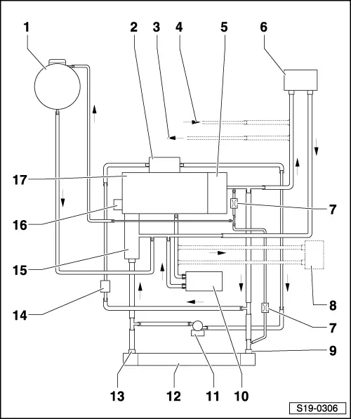
| 1 - | Expansion reservoir |
| q | with cap |
| q | Testing the pressure relief valve in the cap → Chapter |
| 2 - | Radiator for exhaust gas recirculation |
| q | after replacing fill entire system with fresh coolant → Chapter |
| q | removing and installing → Chapter |
| 3 - | to auxiliary heating |
| 4 - | from the auxiliary heating |
| 5 - | Cylinder block |
| q | after replacing fill entire system with fresh coolant → Chapter |
| 6 - | Heat exchanger of heating system |
| q | after replacing fill entire system with fresh coolant → Chapter |
| 7 - | Throttle valve |
| q | integrated into the coolant hose, not visible from the outside |
| q | The fitting position is not defined, therefore the coolant hose must not be unclipped with the hose clamp (Risk of damage!) |
| 8 - | ATF radiator |
| q | only on vehicles with automatic gearbox |
| 9 - | Left coolant hose |
| 10 - | Engine oil cooler |
| q | after replacing fill entire system with fresh coolant → Chapter |
| q | removing and installing → Chapter |
| 11 - | Coolant recirculation pump 2 -V178- |
| q | removing and installing → Chapter |
| 12 - | Radiator |
| q | removing and installing → Chapter |
| q | after replacing fill entire system with fresh coolant → Chapter |
| 13 - | Right coolant hose |
| 14 - | Coolant temperature sender at radiator outlet -G83- |
| 15 - | Coolant regulator |
| q | removing and installing → Chapter |
| 16 - | Coolant pump |
| q | removing and installing → Chapter |
| 17 - | Cylinder head |
| q | after replacing fill entire system with fresh coolant → Chapter |