skoda Workshop Repair Guides

Skoda Workshop Service and Repair Manuals

Timing belt drive - Summary of components > < Removing and installing tensioning element for V-ribbed belt
Removing and installing bracket for auxiliary units
(Octavia II, Yeti)
Special tools and workshop equipment required
t  Supporting device -T30099-
t  Surface -T30099/1-
t  Adapter -MP 9-200/3 (10-222/3)-
t  Ring bolt -3368-
t  Collar nut M10
Removing
–  Remove alternator → Electrical System; Rep. gr.27.
–  Remove the high pressure pump → Chapter.
On vehicles with air conditioning
  WARNING
Do not open the refrigerant circuit of the air conditioning system.
  Note
In order to avoid damage to the AC compressor as well as to the refrigerant lines and hoses, ensure that the lines and hoses are not over-tensioned, kinked or bent.
–  Remove the AC compressor from the bracket for auxiliary units and attach to the lock carrier.
Continued for all vehicles
–  Remove the cooling water tank cover → Body Work; Rep. gr.66.
   
–  Insert the supporting device -T30099- with the base -T30099/1- and the adapter -MP9-200/3- and attach the spindle-B-.
  WARNING
Risk of accident due to loosened screwed connection.
The collar nut must be screwed in by at least 6 turns so that the ring bolt -3368- is held securely.
  S13-0704
–  Tighten the ring bolt -3368- with the collar nut M10 or the nut with the washer -arrow- at the engine support, as shown in the illustration.
–  Hook spindle-A- onto ring bolt -3368-.
–  Uniformly pre-tension the engine with both spindles, but do not raise.
  S13-0707
–  Release screws -1- and -2-, remove connecting stud.
–  Release screws -3...6- and remove engine mounting.
  A13-0647
–  Release screw -3- on engine support.
  A13-10613
–  Release screw -arrow-.
–  Release screws -1- and -2- and remove toothed belt camshaft drives.
  A13-10609
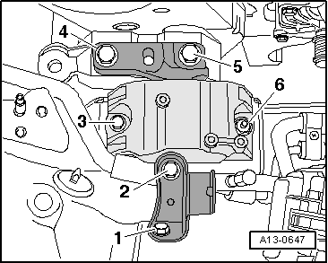
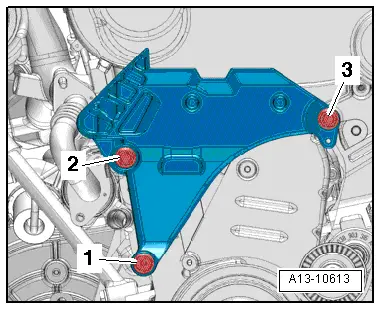
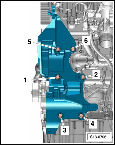
–  Release screws -1 ... 6- and remove bracket for auxiliary units.
Install
Installation is performed in the reverse order, pay attention to the following points:
  Note
Replace screws which have been tightened to a torquing angle.
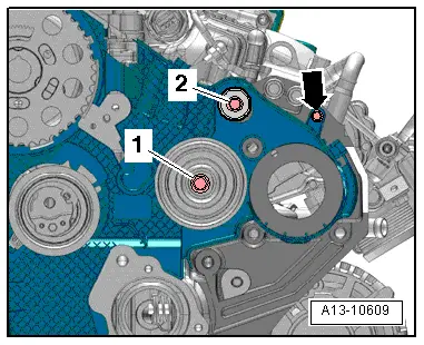
–  If no dowel sleeves are present on the top right between the bracket for auxiliary units and the cylinder block, insert dowel sleeves.
–  Tighten the screws for the bracket for auxiliary units.
t  On vehicles without air conditioning system → Fig..
t  On vehicles with air conditioning system → Fig..
–  Install engine support and engine mount → Chapter and → Chapter.
–  Install high pressure pump → Chapter.
–  Installing the timing belt → Chapter.
–  Install alternator → Electrical System; Rep. gr.27.
On vehicles with air conditioning
–  Install AC compressor at the bracket for auxiliary units → Chapter.
–  Filling and bleeding the fuel system. For this purpose, connect the vehicle diagnosis, measurement and information system -VAS 505x- and carry out the targeted function „bleeding the fuel system“. During this function, the fuel pump is actuated for 180 seconds.
–  Check fuel system for tightness → Chapter.
  S13-0706

Timing belt drive - Summary of components > < Removing and installing tensioning element for V-ribbed belt