skoda Workshop Repair Guides

Skoda Workshop Service and Repair Manuals

Checking hydraulic balancing elements > < Replacing camshaft gasket ring
Removing and installing camshaft
Special tools and workshop equipment required
t  Counterholder -T30004 (3415)-
t  Sealant remover gasket stripper (bearing code GST, bearing article no. R 34402), manufacturer Retech s.r.o.
t  Cleaning and degreasing agent, e.g. -D 009 401 04-
t  Protective goggles and gloves
t  Sealant -D 188 800 A1-
  Note
Observe safety measures and rules for cleanliness when working on vehicles with liquefied petroleum gas system (LPG) → Chapter.
Removing
l  Cylinder head fitted.
–  Removing the intake manifold → Chapter.
–  Remove top toothed belt guard.
   
–  Position camshaft sprocket to TDC marking for cylinder 1 by rotating at crankshaft. The marking on the camshaft sprocket must be aligned with the arrow on the toothed belt guard.
–  Slacken tensioning pulley and take timing belt off camshaft sprocket.
  S15-0351
–  Loosen the camshaft sprocket, to do so use counterholder -T30004 (3415)-.
–  Pull off camshaft sprocket.
–  Remove Woodruff key from the camshaft.
–  Slacken the bolts for the cylinder head cover from the outside to the inside.
–  Remove cylinder head cover.
  S15-0179
–  Unscrew rear toothed belt guard from cylinder head -arrows-.
–  Unscrew the nuts of bearings 5, 1 and 3. Then, slacken bearings 2 and 4 alternately diagonally across.
–  Take off ladder frame.
–  Take out camshaft.
–  Remove the roller rocker arms together with the balancing elements. Lay aside on a clean surface.
–  Ensure that the roller rocker arms and the balancing elements are not mixed up.
  S15-0353
Install
  WARNING
Wear protective gloves when working with sealant and grease remover!
–  Remove the old sealant from the groove -arrow- of the ladder frame as well as from the sealing surfaces and the cylinder head using a chemical sealant remover.
–  Degrease the sealing surfaces.
–  Cut off nozzle tube at the front marking (Ø of nozzle approx. 1 mm).
  S15-0354
–  Insert the hydraulic balancing elements in the cylinder head and position the relevant roller rocker arm on the valve stem ends or balancing elements.
–  Ensure that all the roller rocker arms are correctly positioned on the valve stem ends -1- and are clipped in place on the relevant balancing elements -2-.
–  Oil contact surfaces of camshaft.
  S15-0355
–  Position camshaft in TDC position of cylinder 1:
l  At the camshaft, the cams of cylinder 1 must be pointing up evenly -arrows-.
  S15-0356
–  Apply an even, thin layer of sealant -D 188 800 A1--1- and -2- into the clean groove of the ladder frame.
–  Apply a thin layer of sealant on the surfaces before the ends of the sealant bead -arrows- as well as onto the sealing surface.
  Note
t  The sealant must not be applied too thick. Wipe off any excess sealant with a non-fluffing cleaning cloth.
t  The ladder frame should be fitted on and bolted without any interruption as the sealing surfaces immediately begin hardening as soon as they come into contact.
–  Insert the rear screw cap → Item flush.
  S15-0357
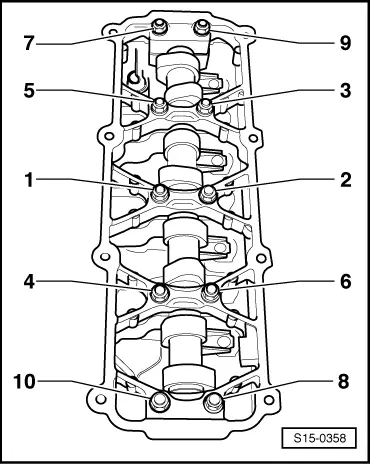
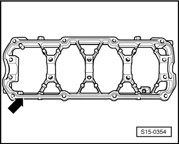
–  Position ladder frame and slightly tighten the nuts -3-, -4-, -5-, -6- in several stages crosswise.
–  Then, slightly tighten the nuts -1-, -2-, -7-, -8-, -9-, -10-.
–  Then tighten the nuts in the sequence -1…10-.
Tightening torque: 23 Nm
–  Replacing camshaft gasket ring → Chapter.
–  install (set the timing) → Chapter.
  Note
t  After installing the ladder frame and the cylinder head cover, allow the sealant to dry for about 30 minutes.
t  After installing the camshaft, the engine must not be started for about 30 minutes. The hydraulic clearance compensation elements must settle (otherwise valves would strike the pistons).
t  After carrying out work on the valve gear, carefully crank engine at least 2 revolutions to ensure that no valve touches the piston when the engine is started.
  S15-0358

Checking hydraulic balancing elements > < Replacing camshaft gasket ring