| –
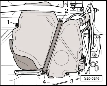
| Release fixing screws -2- and -4- and remove the tensioning strap. |
| –
| Support fuel tank using the engine/gearbox jack -V.A.G 1383 A-. |
| –
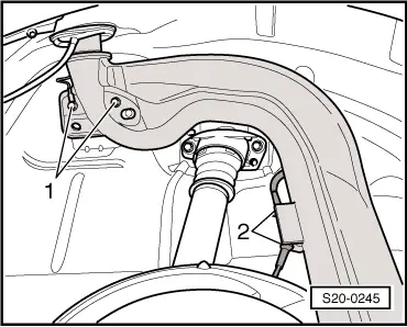
| Release fixing screws -1- and -3-. |
| –
| Slightly lower the fuel tank. |

Note | t
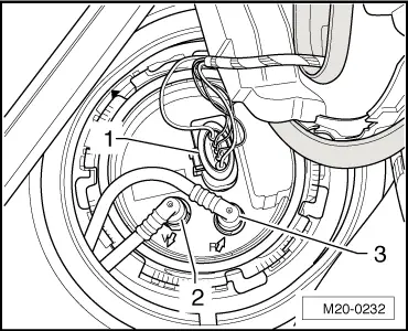
| Pay particular attention to the filler neck and the LPG line in the fuel tank lid unit on vehicles with engine identification characters CHGA. |
| t
| The filler neck must be „extracted“ between structure and rear axle Lift down the fuel tank with a 2nd mechanic from engine/gearbox jack -V.A.G 1383 A-. |
| Installation occurs in reverse order. Pay attention to the following: |
| t
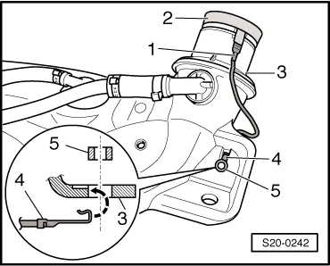
| Lay the vent and fuel lines without any kinks. |
| t
| Do not mix-up the feed line and the return-flow line (the return-flow line is blue or has a blue marking, the feed line is black). |
| t
| Make sure the line connections fit tightly. |
| t
| After installing the fuel tank, check whether the feed, return-flow and vent lines are still clipped in place on the fuel tank. |
| t
| Venting air from the fuel system → Chapter. |
| –
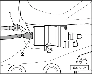
| Check if the earth lead shows traces of oxidation on both connections, remove if necessary. |
|
|
|
 WARNING