| Venting air from the fuel system |

Note | t
| In order to avoid damage to the catalyst, the fuel system without return-flow line must be bled after working on the fuel lines or at the fuel filter. The vehicle can only be started after bleeding. |
| t
| Observe safety measures and rules of cleanliness when working on the fuel supply → Chapter. |
| Special tools and workshop equipment required |
| t
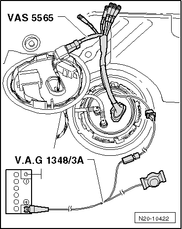
| Remote control -V.A.G 1348/3 A- |
| t
| Adapter for measuring method/DSO (5-pin), e.g. -VAS 5565- |
| t
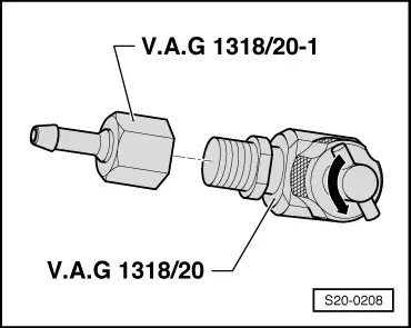
| Adapter -V.A.G 1318/20- |
| t
| Adapter -V.A.G 1318/20-1- |
| t
| Hose clamps 40 mm, e.g. -T30096 (3093)- |

WARNING | The fuel system is under pressure! Before opening the system lay cleaning cloths around the connection point. Reduce pressure by carefully releasing the connection point. |
|
| –
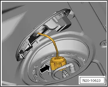
| Remove the cover from the fuel delivery unit. |
Note | For vehicles with auxiliary heating, the plug connection for the dosing pump -V54- must be disconnected additionally. |
|
|
|