
Octavia Mk2
 Note
Note
|
|
|
 WARNING
|
|
|
|
|
|
Note
|
|
|
|
|
|
|
|
|
|
Note
Note
|
|
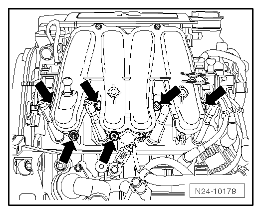
| Component | Nm | |
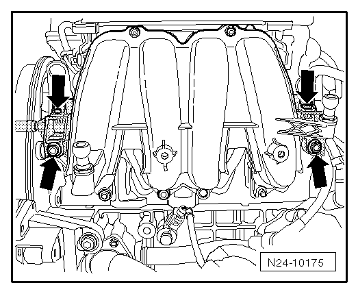
| Intake manifold to cylinder head | 25 | |
| Intake manifold to support | 8 | |
| Bracket for secondary air pump to intake manifold | 8 | |
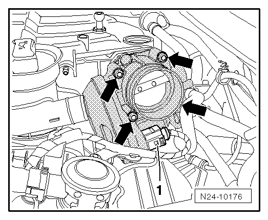
| Throttle valve support to intake manifold | 8 | |
| Gas distributor to intake manifold | 3 | |
|
 Caution