| –
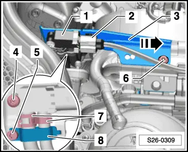
| Disconnect plug connection -2- at exhaust gas pressure sensor 1 -G450--1-. |
| –
| Screw out screw -6- and detach bracket -3- with exhaust gas pressure sensor 1 -G450- in -direction of arrow- from the bracket for the additional fuel pump -V393-. |
| –
| Release screw -5- and remove bracket -8-. |
| –
| Slacken the spring strap clamps -7- and detach the hoses from the connection fittings of the exhaust gas pressure sensor 1 -G450--1-. |
| –
| Screw out screw -4- and loosen the exhaust gas pressure sensor 1 -G450--1- from the bracket -3-. |
| Installation is performed in the reverse order, pay attention to the following points: |

Note | t
| Before installing, blow through the pressure lines to the exhaust gas pressure sensor 1 -G450- with air in order to avoid blockages. |
| t
| Pay attention to the tight fit and leaktightness of the connections. |
| t
| Octavia II, Superb II, Yeti with engine identification characters CEGA → Chapter. |
| t
| Yeti with engine identification characters CBDB → Chapter. |
| The work procedure for the adaptation is described in the „Targeted fault finding“. It is also described under „Targeted functions“. |
| –
| Select the correct vehicle in the targeted fault finding. |
| –
| Press „Selected Functions/Components“. |
| –
| Select „01 - Self-diagnosable systems“. |
| –
| Select „01 - Engine electronics J623“. |
| –
| Select „01 - Engine electronics, function“. |
| –
| Select „01 - Erase initialisation values (Rep. Gr. 21 - 28)“. |
|
|
|
 Caution