skoda Workshop Repair Guides

Skoda Workshop Service and Repair Manuals

Charge-air system - radiator, leaktightness > < Inspect the vacuum system
Replacing and adjusting the vacuum setting element for exhaust turbocharger
Special tools and workshop equipment required
t  10 mm wrench socket -T10422-
t  Ring spanner 10 x 12 -T10423-
t  Socket wrench insert -T40055-
t  Key -T10461-
t  Thin paint brush (approx. 20 cm long)
t  
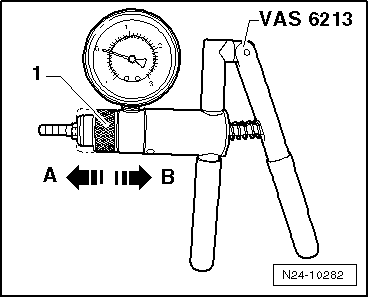
Hand vacuum pump, e.g. -VAS 6213-
  Caution
The special tools listed, in particular the socket wrench -T10422-, must be used exclusively as described below and must not be used for any other screwed connections. Risk of deformations, opening and slipping of the wrench at higher tightening torques.
  Note
In order to replace the vacuum setting element with the position sender for charge pressure regulator -G581- the spare part set is used → Electronic Catalogue of Original Parts.
Removing
–  Remove cover and bulkhead plenum chamber → Body Work; Rep. gr.66.
   
–  Remove the heat shield collar and disconnect the plug -arrow- on the position sender for charge pressure regulator -G581-.
  N15-10406
–  Remove the connecting pipe -1- for the crankcase ventilation from the cylinder head cover, to do so press together the release buttons.
–  Unclip vacuum hoses -arrows-.
–  Release screw -2- (captive), swivel intake hose with connection fitting towards the rear and detach from exhaust gas turbocharger.
–  Close the inlet opening of the exhaust gas turbocharger with a screw cap from the spare part set.
–  Detach vacuum line from vacuum setting element for exhaust gas turbocharger.
  Caution
When slackening the union nut of the oil feed line, it is absolutely essential to counterhold the connection fitting on the exhaust gas turbocharger with the wrench -T10461-.
  A21-10487
–  Unscrew the union nut of the oil feed line -arrow-, to do so counterhold the connection fitting on the exhaust gas turbocharger with the wrench -T10461-.
–  Close the opening of the connection fitting on the exhaust gas turbocharger with a plug from the spare part set.
  N21-10190
–  Unscrew the fixing screws -arrows- and divert the vacuum setting element -A-.
  N21-10268
–  Counterhold the counternut -B- with ring spanner -T10423- and unscrew the adjusting nut -A- from the control rod with socket wrench -T10422-.
Install
  Caution
Only use new screws and nuts from the spare part set.
–  If necessary, remove the bottom adjusting nut from the control rod of the new vacuum setting element.
–  Screw the counternut onto the control rod of the new vacuum setting element by hand up to the thread end and pull the control rod through the opening of the operating lever on the exhaust gas turbocharger.
  Note
Ensure that the operating lever moves smoothly on the control rod.
  N21-10269
–  Move the vacuum setting element -A- in its installed position and screw in fixing screws -arrows-. Tightening torque 8 Nm.
  N21-10268
–  Fit the plug on the position sender for charge pressure regulator -G581--2- and close the heat shield collar.
Adjust the vacuum setting element for exhaust turbocharger
–  Connect vehicle diagnosis, measurement and information system VAS 505x and switch on the ignition.
Select operating mode
–  Press the button „Vehicle self-diagnosis“ on the screen.
Select vehicle system
–  Press the button „01 - Engine Electronics“ on the screen.
The control unit identification and the coding of the engine control unit are indicated on the display.
Select diagnosis function
–  Press the button „011 - Measured values“ on the screen.
–  Enter the measured value block „120“ on the keypad and confirm the entry with the Q key.
  Note
In order to generate „vacuum“, push the ring -1- for the hand vacuum pump -VAS 6213- into position -A-.
  N21-10174
–  Connect the hand vacuum pump -VAS 6213- to the connection of the vacuum setting element.
–  Observe the lowest values of the measured value block and set the voltage to 0.760 V by building up vacuum.
  Caution
During the following setting of the control rod, maintain a steady vacuum and thus also a constant voltage of 0.760 V.
  N24-10282
–  Leave the operating lever in the position »bottom limit« and slowly continue to screw the counternut -B- on the control rod up to the cylinder by hand.
–  Hold the counternut -B-, screw the adjusting nut -A- on the control rod opposite the operating lever and slightly tighten with the ring spanner -T10423-.
–  Reduce the vacuum in the pressure box of the vacuum setting element.
–  Observe the lowest values of the measured value block:
l  If depressurized, the following value must be set: 3.30 ... 3.90 V
–  Tighten the adjusting nut -A- with the socket wrench -T10422-; to do so hold the counternut -B- with the ring spanner -T10423-.
  WARNING
Generate a vacuum of 0.75 ± 0.05 bar at the vacuum setting element to ensure that the operating lever is positioned on the „limit stop“. For this purpose, a voltage of 0.760 V must be set.
If the voltage value is o.k.
  N21-10269
–  Press the lock washer on the control rod by hand and turn it 90° in -direction of arrow-.
–  Apply paint with a thin paint brush from the spare part set to seal the connection of the control rod/adjusting nut.
If the voltage value is not o.k.
  N21-10396
–  Hold the counternut -B-, slacken the adjusting nut -A- and correct the voltage value by turning the counternut -B-.
–  Hold the counternut -B- and tighten the adjusting nut -A- with the socket wrench -T10422-.
  N21-10269
–  Press the lock washer on the control rod by hand and turn it 90° in -direction of arrow-.
–  Apply paint with a thin paint brush from the spare part set to seal the connection of the control rod/adjusting nut.
Finish the installation and check the adjustment
Further installation occurs in reverse order for removal, while paying attention to the following:
–  Remove the plug from the connection fitting on the exhaust gas turbocharger, install the oil feed line and tighten the union nut using the socket wrench insert -T40055-. At the same time counterhold the hexagon of the connection fitting using the wrench -T10461-.
t  Tightening torque 22 Nm.
–  Remove the screw cap from the inlet opening of the exhaust gas turbocharger.
–  Start engine and erase fault memory → Vehicle diagnostic tester.
–  Check the setting as follows:
Select diagnosis function
–  Press the button „006 - Basic setting“ on the screen.
–  Enter the measured value block „120“ on the keypad and confirm the entry with the Q key.
–  Press the button „Activation“ on the screen.
Now the control rod of the vacuum setting element adjusts the operating lever of the exhaust gas turbocharger alternatively to both end positions.
–  Observe the values of the position sender for charge pressure regulator -G581- in the bottom window of the screen:
l  The voltage must oscillate between 0.65 ... 0.85 V and 3.30 ... 3.90 V.
If the voltage values are o.k.:
–  Complete basic setting.
If the voltage values are not o.k.:
–  Correct the setting → Anchor.
  N21-10396

Charge-air system - radiator, leaktightness > < Inspect the vacuum system