skoda Workshop Repair Guides

Skoda Octavia Workshop Service and Auto Repair Manuals

Valve dimensions > < Checking hydraulic balancing elements
Replacing valve stem seals
Special tools and workshop equipment required
t  Valve stem seal extractor -MP1-230 (3364)-
t  Valve stem seal insertion tool -MP1-233 (3365)-
t  Disassembly and assembly device for valve collets -VAS 5161- with knurled spacer ring -VAS 5161/23-1- and guide plate -VAS 5161/23-
t  Screw M6 x 30 (2 pieces)
Work procedure
–  Remove all glow plugs → Chapter.
–  Remove the camshafts → Chapter.
–  When installing again, mark the assignment of the roller rocker arms and the hydraulic clearance compensation elements.
–  Remove the roller rocker arms together with the hydraulic balancing elements and lay aside on a clean surface.
–  Put the piston of the relevant cylinder at „bottom dead centre“.
   
–  Position the guide plate -VAS 5161/23- onto the cylinder head.
–  Screw the guide plate at the side of the intake manifold with the knurled screw -VAS 5161/12- to the cylinder head and with 2 screws M6 x 30 -1- by hand until it fits on tightly.
  N15-10525
–  Screw the sealing bolt -VAS 5161/10- into the guide plate.
–  Screw adapter -VAS 5161/11- into the threaded hole of the glow plug by hand.
  N15-10526
–  Insert the impact drift -VAS 5161/3- into the guide plate and slacken the tightly fitted valve collets using a plastic hammer.
  N15-10527
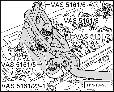
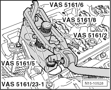
–  Screw the detent part -VAS 5161/6- and the interlocking fork -VAS 5161/5- into the guide plate.
–  Slide the knurled spacer ring -VAS 5161/23-1- onto the assembly cartridge -VAS 5161/8-.
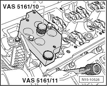
–  Connect the adapter -VAS 5161/11- to the compressed air with a commercially available intermediate piece and apply constant pressure.
l  Minimum pressure: 0.6 MPa (6 bar)
–  Hook the pressure fork -VAS 5161/2- onto the detent part and push the assembly cartridge downwards.
–  Turn simultaneously the knurled screw of the assembly cartridge to the right, until the tips click into the valve collets.
–  Rotate the knurled screw to the left and to the right, by doing so the valve collets are pressed apart and are installed in the assembly cartridge.
–  Release the pressure fork.
–  Remove the assembly cartridge with the knurled spacer ring.
–  Remove the valve spring with the valve spring retainer.
  N15-10528
–  Pull off valve stem seal with extractor for valve stem seal -3364-.
  N15-10538
–  Fit the plastic bushing -A-, which is attached to the new valve stem seals -B-, onto the valve stem.
–  Lightly oil sealing lip of the new valve stem seal.
–  Slide the valve stem seal onto the plastic bushing.
–  Carefully press the valve stem seal with the valve stem seal insertion tool -3365- onto the valve guide.
–  Remove plastic sleeve.
  A15-0282
If the valve collets were removed from the assembly cartridge, first of all they must be inserted into the device -VAS 5161/18-.
l  The large diameter of the valve collets points to the top.
–  Insert the valve spring and the valve spring retainer.
–  Press assembly cartridge -VAS 5161/8- from the top onto the disassembly and assembly device -VAS 5161/18- and lift up the valve collets.
  A15-0445
–  Re-insert the assembly cartridge into the guide plate -VAS 5161/23-.
–  Press down the pressure fork and turn the knurled screw to the left and to the right while pulling it upwards, by doing so the valve collets are inserted.
–  Release the pressure fork on tightened knurled screw.
–  Repeat the procedure for each valve.
Assembling together
Installation is performed in the reverse order, pay attention to the following points:
  Note
Ensure that all the roller arms are correctly positioned on the valve stem ends and are clipped in place on the relevant hydraulic balancing elements.
–  Install camshafts → Chapter.
–  Install glow plugs → Chapter.
  N15-10453

Valve dimensions > < Checking hydraulic balancing elements