| –
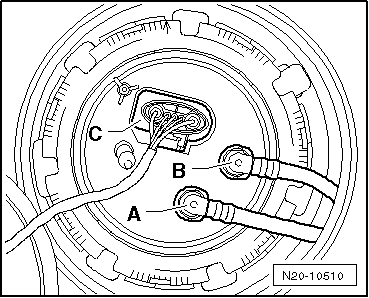
| Open the shut-off cocks „A“ and „B“ of the pressure gauge and close the shut-off cock „C“. |
| –
| Start engine and run in idle. |
| –
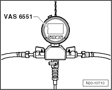
| Close the shut-off cock „B“ for maximum 15 seconds and during this period, read off the pressure at the pressure gauge -VAS 6551-. |
| l
| Specified value: at least 0.05 MPa (0.5 bar). |
| –
| If the injection pressure drops temporarily, replace the fuel delivery pump: |
| t
| Octavia II with front-wheel drive → Chapter. |
| t
| Superb II, Yeti and vehicles with four-wheel drive Octavia II → Chapter. |
| If the specified values are reached: |
| –
| In the event of handling problems, replace the fuel filter, in order to avoid blockage of the fuel filter. |
| If the specified values are not reached: |
| For the vehicles Octavia II, Superb II |
| –
| Remove floor covering under the rear seat bench. |
|
|
|
 Note
Note