Running gearDrive shafts with CV joints
| Repairing drive shaft with CV joint |
| Special tools and workshop equipment required |
| t
| Pressure plate -MP3-406 (VW 401)- |
| t
| Pressure plate -MP3-407 (VW 402)- |
| t
| Pressure spindle -MP3-448 (VW 408 A)- |
| t
| Strutting bushing -MP6-428 (VW 522)- |
| t
| Clamping device -MP6-429- |
| t
| Workshop press, e.g. -V.A.G 1290 A- |
| t
| Tensioning pliers, e.g. -V.A.G 1682- |
|
|
|
| Vehicles up to CW 11 2008 |
| Vehicles as of CW 12 2008 |
| Continued for all vehicles |
| –
| Clamp the drive shaft in a vice with the protective jaws. |
| –
| Remove the CV joint from the drive shaft using a drift -A-. |
| The drift must be positioned exactly at the centre of the CV joint. |
| –
| Remove the disc spring and thrust ring from the drive shaft. |
| Remove outer CV joint of the drive shaft: |
| –
| Push the new joint boot onto the drive shaft. |
|
|

|
| –
| Fit the disc spring -1- and the thrust ring -2- onto the drive shaft. |
|
| Pay attention to correct installation position. |
| –
| Insert new circlip in the groove of the drive shaft. |
| –
| Carefully drive CV joint onto the drive shaft with a plastic hammer until the compressed circlip expands. |
| –
| Grease the CV joint and the joint boot → Anchor. |
| –
| Fit joint boot on the outer joint. |
Diagram not available
Note | t
| In view of the hard material (as opposed to rubber) of the joint boot, which requires the use of stainless steel open warm-type clamps, these can only be tightened with tensioning pliers, e.g. -V.A.G 1682-. |
| t
| Tightening torque 20 Nm. |
| t
| Ensure that the thread of the spindle -A- of the pliers is smooth. Lubricate if necessary with grease. |
| t
| If it is not smooth, e.g. if the thread is dirty, the necessary clamping force of the open warm-type clamp is not reached at the given torque. |
|
|

|
| –
| Tighten the open warm-type clamp on the outer joint (at the large diameter). |
| –
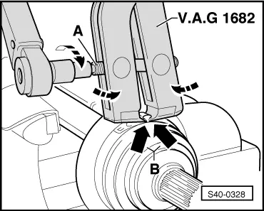
| Apply tensioning pliers, e.g. -V.A.G 1682-, as shown Make sure the cutting edges of the pliers are positioned in the corners -arrows B- of the warm-type clamp. |
| –
| Tighten the warm-type clamp by turning the spindle with a torque wrench. Do not tilt the pliers during this process. |
| A - | Spindle of tensioning pliers |
| B - | Cutting edges of tensioning pliers |
|
|
|
| –
| Tighten the warm-type clamp at the small diameter |
| –
| Apply tensioning pliers, e.g. -V.A.G 1682-, as shown Make sure the cutting edges of the pliers are positioned in the corners -arrows B- of the warm-type clamp. |
| –
| Tighten the warm-type clamp by turning the spindle with a torque wrench. Do not tilt the pliers during this process. |
| A - | Spindle of tensioning pliers |
| B - | Cutting edges of tensioning pliers |
| Vehicles up to CW 11 2008 |
| Vehicles as of CW 12 2008 |
|
|

|
| Vehicles up to CW 11 2008 |
| Vehicles as of CW 12 2008 |
| Continued for all vehicles |
| –
| Remove joint boot from CV joint with drift. |
| –
| Remove the circlip from the drive shaft. |
| –
| Press CV joint off the drive shaft (fig. S40-0098). |
| –
| Do this while supporting the steering joint. |
| –
| Remove the disc spring from the drive shaft. |
|
|

|
| –
| Fit the disc spring -1- onto the drive shaft. |
|
| Pay attention to correct installation position. |
| –
| Push the new joint boot onto the drive shaft. |
|
|

|
| –
| Press CV joint onto the drive shaft up to the stop. |
Diagram not available
Note | Chamfer (chamfered edge) on inner diameter of the ball hub (serration) must point towards the bearing collar of the drive shaft. |
| –
| Fit new circlip on the drive shaft. For this use e.g. the circlip pliers -VW 161 A-. |
| –
| Coat the edge of the inner joint boot cap with sealant - D 454 300 A2-. |
| –
| Fit joint boot on the constant velocity joint. |
Diagram not available
Note | t
| In view of the hard material (as opposed to rubber) of the joint boot, which requires the use of a stainless steel open warm-type clamp, the latter can only be tightened with tensioning pliers, e. g. -V.A.G 1682-. |
| t
| Tightening torque 20 Nm. |
|
|

|
| t
| Ensure that the thread of the spindle -A- of the pliers is smooth. Lubricate if necessary with grease. |
| t
| If it is not smooth, e.g. if the thread is dirty, the necessary clamping force of the open warm-type clamp is not reached at the given torque. |
| Vehicles up to CW 11 2008 |
| Vehicles as of CW 12 2008 |
|
|
|
01 Steering & suspension