skoda Workshop Repair Guides

Skoda Workshop Service and Repair Manuals

Gearbox mechanics,operation, construction,diff. > < Technical Data for the Gearbox
Adjust the position of the engaging bearings for clutch „K 1 and K 2“ - „old design“ up to 05.11
Special tools and workshop equipment required
t  Gauge block -T10374-
t  Straightedge -T40100-
t  Adhesive -AMV 195 KD1 01-
t  Digital depth gauge
The position of the engaging lever must be adjusted if:
t  The clutch was replaced
t  The engaging levers were replaced
t  The engaging bearing was replaced.
   
t  the support is also part of the control.
If all the mentioned parts are only removed and reinstalled, there is nothing to adjust.
Conditions
l  Only use proper tools.
l  The flange of the clutch housing must be free of »irregularities«. This ensures a good position of the straightedge.
l  The mechatronics is installed.
Short description
The position of the engaging bearing is comparable with the clutch play of a mechanical manual gearbox. In the automatic gearbox DSG - 0AM, tolerances are present in the engaging system of the gearbox and in the gearbox itself. The tolerances also exist inside the double clutch. These tolerances must be considered separately when adjusting.
In the following procedure is first shown how to establish all the necessary dimensions on the »gearbox side« in order to determine the suitable adjusting washer. The tolerances on the gearbox side and the tolerances in the clutch determine the thickness of the adjusting washer.
First a dimension „B“ must be established. This dimension is required for both clutches »K 1« and »K 2«.
In addition, a dimension „A“ is established for each clutch. The following figures N30-10291 and N30-10292 show where to measure these dimensions.
  Note
The adjusting washer for the clutch „K1“ is installed on the large bearing, the adjusting washer for the clutch „K2“ is installed under the small bearing.
  N30-10259
»K 1«
  N30-10291
»K 2«
  Note
Perform the following work steps accurately and »in sequence«.
Setting
  N30-10292
–  Install the parts of the clutch up to the large engaging lever → Chapter.
Do not install the small engaging bearing and do not insert an adjusting washer.
  N30-10264
–  Install the circlip of the outer drive shaft -arrow-.
  N30-10277
–  Place the ruler -T40100- upright on the flange of the clutch housing.
  Note
The measuring ruler -T40100- must remain in this position during the following measurements. Do not turn or remove it.
  N30-10278
–  Position the digital depth gauge-A- on the outer drive shaft -B-.
–  Set the depth gauge to »0«.
  S30-0220
–  Measure the distance to the circlip.
–  Note the result and name it „B“.
As an example: „B“ = 2.91 mm
  N30-10279
–  Measure the dimension „B“ once more at the opposite-facing point.
  Note
Do not measure on the joint of the ring. The ring could be pressed off from the joint and thus the measuring result will be inaccurate.
–  Remove the circlip again.
This ring must not be reinstalled!
–  Determine the mean value from both measurement results.
As an example:
   Dimension „B“ =
B1+B2
2
=
2,91+3,0
2
= 2.96
This dimension „B“ is required for the following calculations.
In the following example calculations „B“ should be = 2,96 mm. The dimension „B“ is for this example, there can be another value „B“ for different gearboxes.
As there are 2 clutches, 2 steps are performed for the adjustment.
Each measurement requires different preparatory measures, including a few calculations. Please observe the following work procedures.
  N30-10280
First determine the adjusting washer for the large engaging bearing for the clutch „K1“.
  WARNING
Do not insert an adjusting washer!
  N30-10291
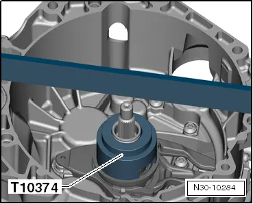
–  Position the gauge block -T10374- on the »large« engaging bearing.
–  Press on the gauge block -T10374- once and turn it at the same time.
In this way one can observe how the engaging bearing turns. Thus, the gauge block -T10374- is also »positioned« correctly on the bearing.
  N30-10284
–  Position the digital depth gauge at the »top« on the outer drive shaft and set the digital depth gauge to „0“.
The ruler -T40100- is already positioned »upright« on the flange of the clutch housing → Anchor.
  N30-10281
–  Measure the distance from the »shaft end« to the gauge block -T10374-.
  N30-10282
–  Position the digital depth gauge twice at opposite-facing points for a precise measurement.
In this way, an even more precise value is determined as the inaccuracy resulting from the »wobbling« on the engaging bearing is thus minimised.
–  Calculate the mean value of both measurements to the gauge block -T10374-.
–  Note this value and name it „A1“.
As an example:
   Dimension „A1“ =
2,61+2,81
2
= 2.71
As an example: „A1“ = 2.71 mm
The following calculation:
„A1“ minus „B“ plus height of the gauge block -T10374- = depth of the engaging bearing of clutch 1.
The height of the gauge block -T10374- is always the same. It is: 51.81 mm.
Example calculation:
2,71 mm minus 2.96 mm plus 51,81 mm = 51,56 mm.
You have now determined the value of how deep the engaging bearing is actually positioned in the gearbox.
The depth of the bearing must be 50.08 mm on each gearbox.
The nominal dimension „50,08 mm“ is deducted from the actual dimension. Thus, the actual air passage of clutch 1 is determined.
–  Continue the calculation:
The determined value (in the example: 51,56 mm) minus the nominal value = the air passage of the clutch.
Example calculation:
51,56 mm minus „50,08 mm“ = air passage of clutch 1 = 1,48 mm.
Now the tolerances in the double clutch must be included in this calculation. This is a very simple procedure:
  N30-10283
–  Please read off the value of the clutch tolerance -arrow- from the »new« clutch.
A value between minus 0.40 and plus 0.40 mm is marked on the new clutch.
–  Note this value.
Example 1: „-0,40 mm“ is given on the clutch.
The last calculation for »K 1«: »Its determined« air passage minus the value of clutch 1 =
1,48 mm minus 0.40 = 1,08 mm.
Example 2: „+0.20 mm“ is given on the clutch.
Then the last calculation for »K 1« is done as follows: 1,48 mm plus 0.20 = 1,68 mm.
–  Select the correct washer from the table and install it.
  S30-0223
Determined thickness of the washerWasher to be installed in mm
fromto 
0,310,900,8
0,911,101,0
1,111,301,2
1,311,501,4
1,511,701,6
1,711,901,8
1,912,102,0
2,112,302,2
2,312,502,4
2,512,702,6
2,713,302,8

   
–  From the delivered washers, determine the adjusting washer which is required.
  WARNING
At a later stage, just insert this 1 adjusting washer. Do not insert 2 washers.
Thus, the »correct« adjusting washer for „K 1“ is determined. Please install this adjusting washer when installing the clutch at a later stage.
–  Proceed with the adjustment for the clutch „K 2“.
  N30-10156
Determine the adjusting washer for the small engaging bearing for the clutch „K 2“.
  N30-10292
–  Only insert the small bearing.
  WARNING
Do not insert an adjusting washer!
  N30-10262
The small engaging bearing fits in only one position due to the 4 grooves.
  N30-10232
–  While »turning«, check if the small engaging bearing is correctly installed and the grooves are correctly positioned.
  N30-10261
–  Position the gauge block -T10374-»with the large opening upwards« on the small bearing.
  N30-10286
–  Place the digital depth gauge at the »top« on the outer drive shaft.
–  Reset the depth gauge to »zero«.
  N30-10287
–  Measure the distance from the »shaft end« to the gauge block -T10374-.
  N30-10288
–  Position the digital depth gauge twice at opposite-facing points for a precise measurement.
In this way, an even more precise value is determined as the inaccuracy resulting from the »wobbling« on the engaging bearing is thus minimised.
–  Calculate the mean value of both measurements to the gauge block -T10374-.
–  Note this value and name it „A2“.
As an example:
   Dimension „A2“ =
2,50 + 2,54
2
= 2.52
As an example: „A2“ = 2.52 mm
The following calculation:
„A2“ minus „B“ plus height of the gauge block -T10374- = depth of the engaging bearing of clutch 2.
The height of the gauge block -T10374- is always the same. On the inside, it is: 36.20 mm.
Example calculation:
2.52 mm minus 2.96 mm plus 36.20 mm = 35.76 mm.
You have now determined the value of how deep the engaging bearing is actually positioned in the gearbox.
The depth of the bearing must be 34.35 mm on each gearbox.
The nominal dimension „34.35 mm“ is deducted from the actual dimension. Thus, the actual air passage of clutch 2 is determined.
–  Continue the calculation:
The determined value (in the example: 35.76 mm) minus the nominal value = the air passage of the clutch.
Example calculation:
35.76 mm minus „34.35 mm“ = air passage of clutch 2 = 1.41 mm.
Now the tolerances in the double clutch must be included in this calculation. This is a very simple procedure:
  N30-10289
–  Please read off the value of the clutch tolerance -arrow- from the »new« clutch.
A value between minus 0.40 and plus 0.40 mm is marked on the new clutch.
–  Note this value.
Example 1: „- 0.40 mm“ is given on the clutch.
The last calculation for »K 2«: »Its determined« air passage minus the value of clutch 2 =
1.41 mm minus 0.40 = 1.01 mm.
Example 2: „+ 0.20 mm“ is given on the clutch.
Then the last calculation for »K 2« is done as follows: 1.41 mm plus 0.20 = 1.61 mm.
–  Select the correct washer from the table.
  S30-0223
Determined thickness of the washerWasher to be installed in mm
fromto 
0,310,900,8
0,911,101,0
1,111,301,2
1,311,501,4
1,511,701,6
1,711,901,8
1,912,102,0
2,112,302,2
2,312,502,4
2,512,702,6
2,713,302,8

   
–  From the delivered washers, determine the adjusting washer which is required.
  WARNING
At a later stage, just insert this 1 adjusting washer. Do not insert 2 washers.
Thus, the »correct« adjusting washer for „K 2“ is also determined. Please install this adjusting washer when installing the clutch at a later stage. This washer belongs under the small engaging bearing.
–  The clutch can be installed → Chapter.
  N30-10156

Gearbox mechanics,operation, construction,diff. > < Technical Data for the Gearbox