skoda Workshop Repair Guides

Skoda Workshop Service and Repair Manuals

The vane pump for vehicles fitted with a 6 cylinder petrol engine > < Bleeding brake system
Removing and installing steering column
Removing:
  WARNING
Disconnect earth strap from the battery with the ignition off before commencing work on the electrical system.
Observe the instructions before reconnecting the battery → Electrical System; Rep. Gr.27.
The steering column is supplied as a spare part in the form of a complete assembly. Repairs are not allowed!
The ignition lock housing can be modified.
–  Disconnect battery → Electrical System; Rep. Gr.27
–  Remove the steering wheel → Body work; Rep. Gr.69.
–  Remove the resetting ring together with the slip ring → Body work; Rep. Gr.69
Vehicles with ABS/EDL/TCS/MSR/ESP
–  Removing steering angle sender -G85- → Chapter
Continued for all vehicles
–  Removing steering-column control → Electrical System; Rep. Gr.94
   
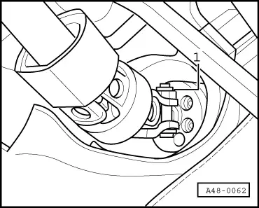
–  Remove the plug -arrow- from the steering lock housing.
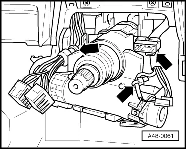
   In the case of vehicles fitted with automatic gearbox, the interlock designed to prevent ignition from being switched on must also be removed from the ignition lock → Anchor
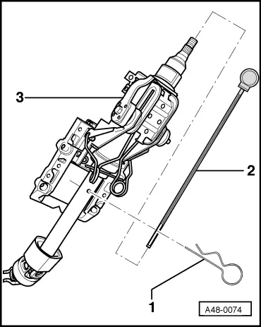
Secure the steering column before removal
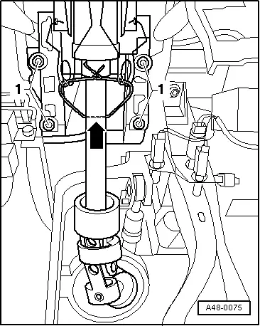
An assembly securing device is required to prevent the lower and the upper part of the steering column from separating during removal of the steering gear.
If the upper and the lower parts of the steering column are separated too widely or are pushed into one another then the gearing system will become separated.
This could cause rattling noises during operation at a later stage if the gear teeth are no longer in their original installed position.
–  Remove the storage area on the driver's side → Body Work; Rep. Gr.70
  A48-0061
–  Pull a wire through the bore on the lower side of the steering column -arrow- and the spring
The steering column can also be secured by means of a transport protection device → Anchor
  A48-0075
–  Remove nut -1- on the universal joint.
–  Slacken the screw (Torx T50) by turning clockwise and then release screw.
–  Remove the universal joint from the steering gear.
  A48-0062
–  Remove the screws -1- on the steering column and take out the steering column.
–  Remove the steering lock housing → Chapter
Installing:
New steering columns supplied as spare parts are secured for transport.
  A48-0075
This transport protection device must be removed after installing the steering column in the vehicle.
1 - Release pin
2 - Plastic rod
3 - Steering column
We recommended that you keep these components in safe keeping. They may be needed to remove the steering column.
  A48-0074
–  Position the new steering column on the cross member using 4 screws -1-.
–  Insert the universal joint onto the steering gear pinion.
–  Insert the screw (Torx 50) through the lower part and pretension by turning it anti-clockwise.
–  Position and tighten a new nut.
–  Remove wire/transport protection device between the upper and the lower parts of the steering column.
–  Install the steering lock housing → Anchor
–  Install the steering-column control → Electrical System; Rep. Gr.94
–  Align the steering column so that the joint on the casing are uniform throughout.
  A48-0075
–  Tighten the screws -1- of the steering column.
–  Install the storage area on the driver's side → Body Work; Rep. Gr.70
–  Install resetting ring together with slip ring → Body work; Rep. Gr.69
–  Installing steering angle sender -G85- → Chapter
–  Install steering wheel → Body work; Rep. Gr.69
–  Connect battery → Electrical System; Rep. Gr.27
Steering columns supplied as spare parts do not have dotting marks.
Thus the central position of the steering wheel must be determined with -V.A.G 1907- if necessary, → Chapter.
  A48-0075
Tightening torques:
Steering column to cross member22 Nm
Universal joint of the steering column to power-steering gear
t  Use new nut!
40 Nm


The vane pump for vehicles fitted with a 6 cylinder petrol engine > < Bleeding brake system