
Superb
|
|
|
|
|
|
|
|
|
|
|
| Tightening torques: |
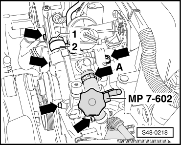
| Vane pump to the holder | 22 Nm | ||
| Bracket for vane pump to cylinder block | 22 Nm | ||
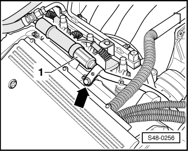
| Hollow screw for the pressure line | 50 Nm | ||
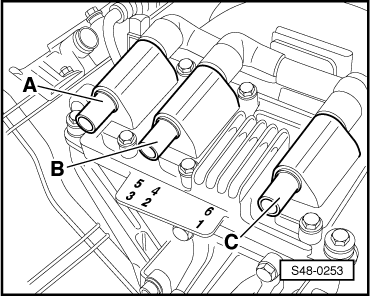
V-belt pulley to the vane pump
| 22 Nm | ||
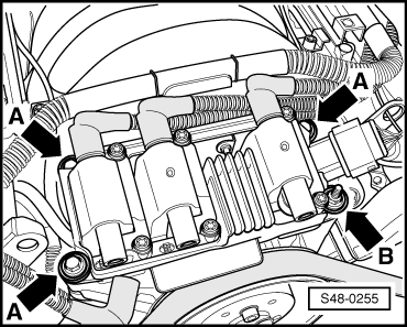
| Ignition coil to the holder of the vane pump. | 10 Nm |