skoda Workshop Repair Guides

Skoda Workshop Service and Repair Manuals

Enginecrankshaft group, pistons > < Self diagnosis, safety measures, cleanliness regulations and directions
Instructions for removal
–  Remove engine cover.
–  Remove the connecting pipe between the charge air cooler and the intake
–  Pull the fuel feed line (with the white markings) and return line (with the blue markings) off the fuel lines (which is clipped onto the bulkhead) and catch the fuel which leaks out with a cleaning rag.
–  Drain coolant → Chapter.
–  Removing the lock carrier → Body Work; Rep. Gr.50.
–  Remove V-ribbed belt → Chapter.
–  Unclamp connecting, cooling fluid, vacuum and suction hoses from the engine.
–  Remove/unclamp all electrical lines from the gearbox, generator and starter motor and uncover them.
–  Remove/unclamp all other necessary electrical cables from the engine.
–  Unbolt front exhaust pipe from exhaust turbocharger → Chapter.
–  Unscrew the compensation bottle from the cooling system and place it to the side.
–  Unscrew the vane pump for the power-assisted steering at its holder and place it to the side; hoses should remain connected up → Chassis; Rep. Gr.48.
–  Observe supplementary instructions and assembly work.
–  Remove the starter → Electrical System; Rep. Gr.27.
Vehicles with automatic gearbox
   
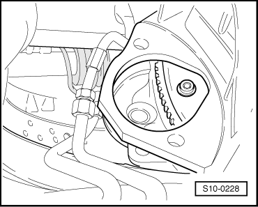
–  Unscrew the torque converter from the driver plate, do this by screwing out the screws through the starter opening (the crankshaft must be further turned by 1/3rd of a turn in its direction of rotation of engine).
  Note
t  To loosen the screws on the torque converter counterhold at the central screw of the V-ribbed belt pulley.
t  When removing the engine, counterhold the torque converter through the starter opening in the gearbox with the help of a second mechanic.
t  Secure the torque converter before removing the engine against “dropping down”.
Continued for all vehicles
–  Remove the upper engine/gearbox connecting screws.
  Note
Just loosen a connecting screw, but do not screw out immediately.
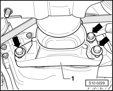
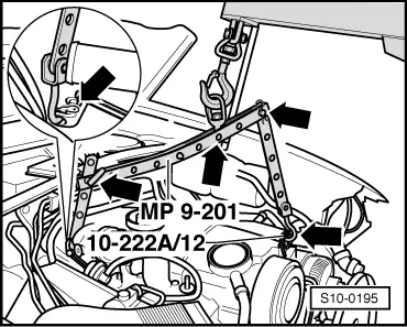
–  Unscrew the fixing screws for the engine mounting on the upper right and left.
  S10-0228
–  Unbolt the dead stop -1--arrows-.
  S10-0229
–  Screw the original screw with the three original washers (all 4 mm thick) modified mount -T10062- through the middle hole -arrow- onto the oil pan on the right and tighten the connection to 30 Nm.
–  Lift up the engine and gearbox with installed mount -T10062- using engine/gearbox lifter -V.A.G 1383 A- sufficiently in order to be able to remove the lower connecting screws on the engine/gearbox.
–  Remove the connecting screws on the engine/gearbox at bottom and lower the assembly again.
  S10-0230
–  Install supporting device -MP 9-200- with its additional hooks -10-222A/12- as shown in figure.
–  Hook the gearbox mount -T30062- into the screw hole of the gearbox bell (shown in the figure on removed engine).
  S10-0194
–  Hook on the suspension fixture -MP 9-201- as follows and raise slightly with the workshop crane -V.A.G 1202 A-.
On the belt pulley side: 5th hole of the extension - 10-222A/12 - in Position 1.
On the flywheel side:3rd hole of the perforated bar in position 8
Hook: in position 3 of supporting bracket
  WARNING
Use securing pins on the hooks and rig pins to prevent release.
  Note
t  The rig positions on the supporting bracket marked 1...8 point towards the belt pulley.
t  The holes in the perforated bars and extension are counted from the hook.
–  Remove the upper engine/gearbox connecting screw.
–  Lift out engine toward front.
  Note
Engine and gearbox must be guided carefully when lifted out, in order to avoid damage.
For carrying out removal and installation work, the engine should be secured with the distance sleeves -T30010- in the engine mount - MP 1-202- at the assembly stand -MP 9-101-.
  S10-0195

Enginecrankshaft group, pistons > < Self diagnosis, safety measures, cleanliness regulations and directions