
Superb
| Removing and installing the fuel tank with its component parts |

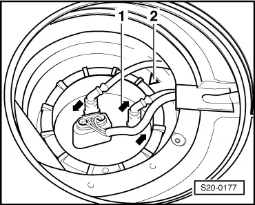
| 1 - | Screw plug |
| 2 - | Sealing ring |
| q | replace if damaged |
| 3 - | Fuel tank lid unit |
| q | with rubber bowl |
| q | removing and installing → Body Work → Rep. Gr.55 |
| 4 - | Fixing screw |
| 5 - | Gravity valve |
| q | unclip out of the support at the top |
| q | inspect valve for blockage: |
| t | Valve in a vertical position: open |
| t | Valve tilted 45°: closed |
| 6 - | O-ring |
| q | replace if damaged |
| 7 - | Vent line |
| q | black |
| q | clipped in place on the side of the fuel tank |
| q | check for firm seating |
| q | secure with spring strap clamps |
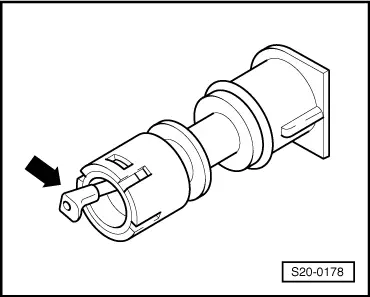
| 8 - | Vent valve |
| q | to remove, unclip valve at side and take out of filler neck. |
| q | before installing, unscrew cap → Item |
| q | check → Fig. |
| 9 - | Earth connection |
| 10 - | Vent line |
| q | check for firm seating |
| 11 - | 25 Nm |
| 12 - | Fuel tank |
| q | when removing, support e.g. with the engine/gearbox jack -V.A.G 1383 A - |
| q | removing and installing → Chapter |
| 13 - | Support |
| q | for straps |
| q | Check fitting position |
| 14 - | 5 Nm |
| 15 - | Fuel cooler |
| q | attached to the underfloor of the body |
| 16 - | Tensioning strap |
| q | pay attention to different lengths |
| 17 - | Sealing ring |
| q | to be inserted dry into the opening of the fuel tank |
| q | replace if damaged |
| q | only moisten the seal of the flange with fuel for fitting purposes |
| 18 - | Fuel delivery unit |
| q | with sender for fuel gauge display |
| q | Fitting position → Fig. |
| q | removing and installing → Chapter |
| q | Check fuel delivery unit → Chapter |
| q | Clean strainer if dirty |
| q | removing and installing the sender for fuel gauge → Chapter |
| 19 - | Return-flow line |
| q | with branch piece from additive container → Chapter |
| q | clipped on the fuel tank |
| q | check for firm seating |
| q | blue |
| 20 - | Feed line |
| q | to fuel filter → Chapter |
| q | clipped on the fuel tank |
| q | check for firm seating |
| q | black |
| 21 - | Union nut, 80 Nm |
| q | remove and install using wrench for union nut -MP1-227 (3217)- |
 Note
Note
|
|