
Superb
| 1) Adjustments need to be made when replacing these parts. Setting overview → Chapter. |
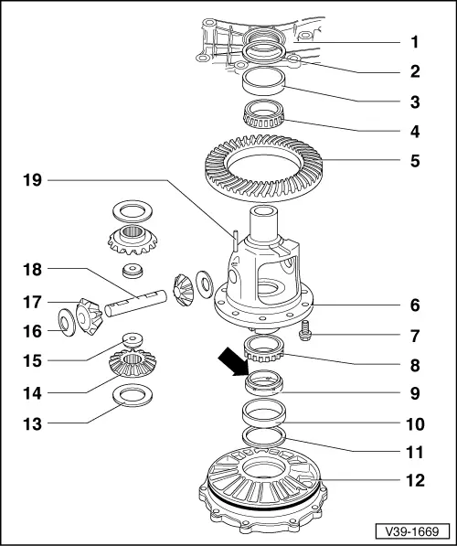
| 1 - | Gearbox housing1) |
| 2 - | Adjusting washer S2 |
| q | Note thickness |
| q | Setting overview → Chapter |
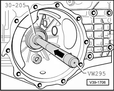
| 3 - | Outer ring/taper roller bearing, small1) |
| q | extracting → Fig. |
| q | inserting → Fig. |
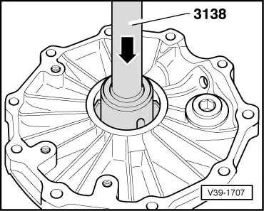
| 4 - | Inner ring/taper roller bearing, small1) |
| q | remove → Fig. |
| q | pressing on → Fig. |
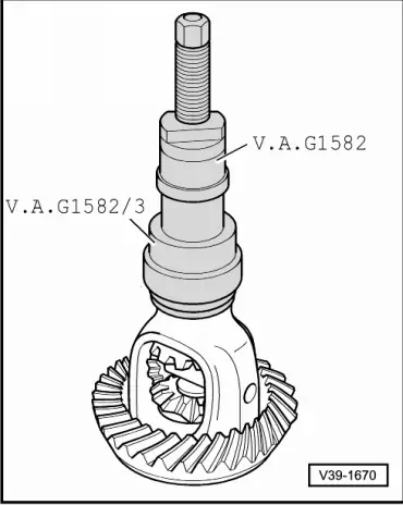
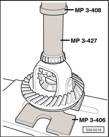
| 5 - | Crown wheel1) |
| q | paired with secondary shaft (drive train) |
| q | according to gearbox identification characters → Chapter assign via the → Electronic Catalogue of Original Parts. |
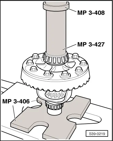
| q | drive out with drift pin → Fig. |
| q | mounting on differential housing → Fig. |
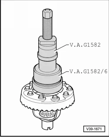
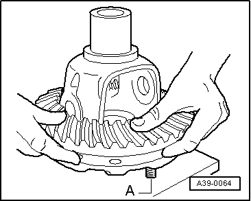
| 6 - | Differential1) |
| 7 - | 60 Nm and turn a further 45° |
| q | always replace → Electronic Catalogue of Original Parts |
| q | use original replacement parts only |
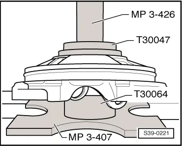
| 8 - | Inner ring/taper roller bearing, large1) |
| q | remove → Fig. |
| q | pressing on → Fig. |
| 9 - | Drive wheel for speedometer |
| q | removing and installing → Chapter |
| q | Fitting position: Collar -arrow- points towards differential gear; catch studs in recess of differential gear housing |
| q | do not tilt |
| 10 - | Outer ring/taper roller bearing, large1) |
| q | extracting → Fig. |
| q | inserting → Fig. |
| 11 - | Adjusting washer S1 |
| q | Note thickness |
| q | Setting overview → Chapter |
| 12 - | Cover1) |
| q | for final drive |
| q | with O-ring seal |
| q | Replace O-rings → Electronic Catalogue of Original Parts |
| q | Lubricate O-ring seal when installing |
| 13 - | Adjusting washer |
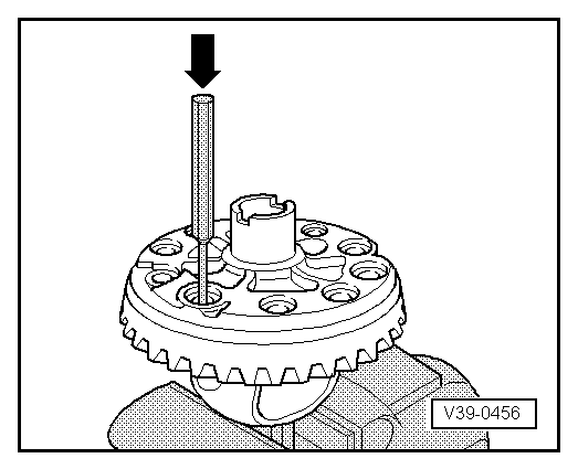
| q | Determining thickness again → Fig. |
| 14 - | Differential bevel gear large |
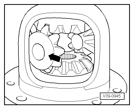
| q | installing → Fig. |
| q | adjust → Fig. |
| 15 - | Threaded part |
| 16 - | Thrust washer |
| q | check for breaks or cracking |
| 17 - | Differential bevel gear small |
| q | installing → Fig. |
| q | adjust → Fig. |
| 18 - | Differential bevel gear shaft |
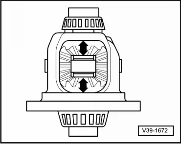
| q | after removing tensioning pin Pos. 19, drive out with drift pin |
| q | before inserting, align thrust washers |
| 19 - | Tensioning pin |
| q | always replace → Electronic Catalogue of Original Parts |
| q | insert flush |
|
|
|
|
|
|
|
|
|
|
|
|
 Caution
|
|
 Note
Note
Note |
|
|

|
| Adjusting washer thickness (mm) | ||
| 0,50 | 0,70 | 0,90 |
| 0,60 | 0,80 | 1,00 |
|

|
|
|
|
|
|
|