skoda Workshop Repair Guides

Skoda Workshop Service and Repair Manuals

Testing fuel pump > < Removing and installing parts of the fuel supply system
Check fuel flow rate
Test conditions
l  Voltage supply o.k.
l  Remote control -V.A.G 1348/3A- connected
Test sequence
–  Take cap off fuel filler neck.
–  Remove intake hose cover.
  WARNING
The fuel feed line is pressurized! Place cleaning cloths around the connection point before detaching hose connections. Reduce pressure by carefully removing the hose.
   
–  Open screwed connection -arrow- and catch the fuel which flows out with a cloth.
  N20-0145
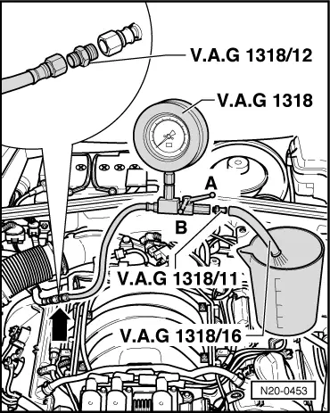
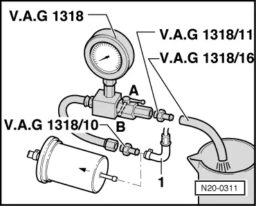
–  Connect the pressure gauge - V.A.G 1318- with the adapter -V.A.G 1318/12- to the fuel feed line.
–  Fit the hose -V.A.G 1318/16- onto the adapter -V.A.G 1318/11- of the pressure measuring device and hold it in a measuring glass.
–  Open shut-off cock of the pressure gauge. The lever then points in the direction of flow -A-.
–  Activate remote control -V.A.G 1348/3 A-. While doing so, slowly close the shut-off cock until the pressure gauge displays 0.4 MPa (4 bar) overpressure. Now do not make any further changes to the position of the shut-off cock.
–  Empty measuring glass.
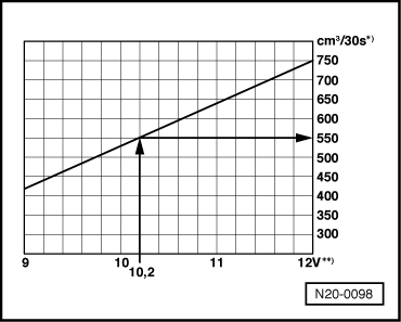
–  The fuel flow rate of the fuel pump is dependent on the battery voltage. Therefore connect the multimeter with adapter cables from the measuring tool set, e.g. -V.A.G 1594 C-, to the vehicle battery.
–  Activate remote control for 30 seconds while measuring the battery voltage.
  N20-0453
–  Compare the fuel rate with the specified value.
*) - Minimum delivery cm3/30 s
**) - Voltage at fuel pump when engine not running and pump operating (approx. 2 V less than battery voltage).
Read out examples:
During the test a voltage of 12.2 V was measured on the battery. As the voltage on the pump is approximately 2 volts less than the battery voltage, a minimum flow rate of 550 cm 3/30 s is obtained.
If the minimum delivery volume is not reached:
–  Check the fuel lines for possible restrictions (kinks) or blocking.
  N20-0098
–  Disconnect the feed line -1- from the fuel filter.
–  Connect the pressure gauge -V.A.G 1318- with the adapter -V.A.G 1318/10- to the hose.
–  Repeat flow rate test.
If the minimum flow rate is now reached:
–  Replace fuel filter.
If the minimum delivery volume is still not reached:
–  Remove fuel delivery unit and inspect the filter strainer for soiling → Chapter.
If you have still not found any fault up to this stage:
–  Replace defective fuel delivery unit → Chapter.
If the required delivery volume has been achieved, but a fault is still suspected in the fuel supply system (e.g. intermittent breakdown of the fuel supply).
Check the power consumption of the fuel delivery unit as follows:
–  Connect all released fuel lines.
–  Remove the cover from the fuel delivery unit.
–  Disconnect the 4-pin plug from the flange of the fuel delivery unit.
  N20-0311
–  Set the multimeter to the measurement range 20 A and install it in series using adapter cables from the measuring tool set, e.g. -V.A.G 1594 C- between the contacts -1- of the connector and the fuel pump.
  Note
One can also connect the current probe of the multimeter -V.A.G 1715- or of the vehicle diagnosis, masurement and information system -VAS 5051- to the adapter cables between the contacts -1- of the connector and the fuel pump.
–  Connect contacts -4- from connector and fuel pump with an auxiliary cable from the measuring tool set, e.g. -V.A.G 1594 C-.
–  Start engine and run in idle.
–  Measure power consumption of the fuel delivery unit.
   Specified value: max. 8 A
  Note
If the fault in the fuel supply system is intermittent then tests can be undertaken during a test drive but then two people are required for this.
If the specfied current uptake is exceeded:
–  Replace defective fuel delivery unit → Chapter.
  M20-0079

Testing fuel pump > < Removing and installing parts of the fuel supply system