
Repairing Air Conditioning: Engine Compartment
| Repairing the air conditioning system - engine compartment |
 Note
Note| t | All air conditioning components marked * as well as all refrigerant hoses and refrigerant lines must be repaired in specialist service centres which have suitably trained personnel and are fitted out for working on the refrigerant circuit. |
| t | Comply with the safety measures when working on vehicles with air conditioning system and when using refrigerant R 134a and observe the instructions for working on the refrigerant circuit → Air conditioning system with refrigerant R134a; Rep. gr.00 technical data. |
| t | The engine must not be started if the refrigerant lines are not connected to the compressor and the compressor is shut off with plugs (risk of overheating because of the internal refrigerant oil circuit). |
| t | If the refrigerant circuit was separated, it is not always necessary to replace the dessicator, see → Chapter. |
| t | If the earth strap of the battery was disconnected, pay attention to the sequence when connecting it → Electrical System; Rep. gr.27. |
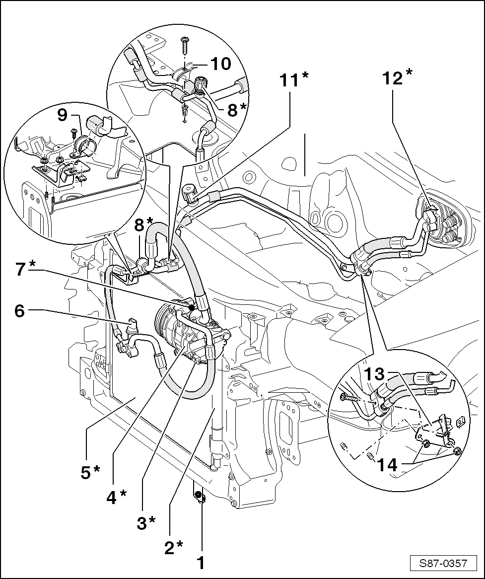
| 1 - | Ambient temperature sensor -G17- |
| q | removing and installing → Chapter |
| q | check → Vehicle diagnostic tester |
| q | Fitting location: below the front left bumper at the bumper support |
| 2 - | Fluid container with dessicator insert* |
| q | removing and installing → Chapter |
| q | Replace fluid reservoir with dessicator / dessicator insert, if… → Chapter |
| 3 - | Regulating valve for compressor, air conditioning system - N280-* |
| q | Elements of the compressor, do not replace individually |
Note| Depending on the required cooling output the regulating valve receives a PWM signal (500 Hz) from the Climatronic control unitair conditioning control unit -J301- or from the Climatronic control unit -J255- and regulates the displacement of the compressor via the suction pressure/position of the articulated disc. |
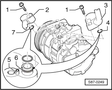
| 4 - | Compressor* |
| q | different manufacturers and oil capacities: → Chapter |
| q | Removing and installing the refrigerant lines → Fig. |
| q | Belt protection for blocked compressor → Chapter |
| q | Removing and installing the compressor → Chapter |
| q | Running-in instruction → Chapter |
| 5 - | Condenser* |
| q | Removing and installing the refrigerant lines → Fig. |
| q | Removing and installing the condenser → Chapter |
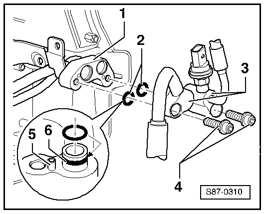
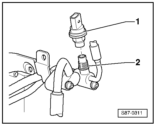
| 6 - | High-pressure sender -G65- |
| q | function → Chapter |
| q | removing and installing → Fig. |
| q | inspect → Vehicle diagnostic tester in the function „Targeted fault finding“ |
| 7 - | Pressure relief valve* |
| q | Replace O-ring ( → Electronic Catalogue of Original Parts). |
| q | Tightening torque: 10 Nm |
| q | function → Chapter |
| q | check → Chapter |
| 8 - | Extractor and filling valve* |
| q | High-pressure side |
| q | for exhausting, filling and measuring |
| q | Contents → Chapter |
| q | always screw on cap with gasket |
| q | Description, removing and installing → Chapter |
| 9 - | Clamp |
| 10 - | Retaining clip |
| 11 - | Exhaust valve* |
| q | Low-pressure side |
| q | for exhaust and measurement only |
| q | always screw on cap with gasket |
| q | Description, removing and installing → Chapter |
| 12 - | Expansion valve* |
| q | removing and installing → Chapter |
| 13 - | Holder for refrigerant lines |
| 14 - | 20 Nm |
Note
|
|
Note
|
|
Note
|
|