skoda Workshop Repair Guides

Skoda Workshop Service and Repair Manuals

Check gear oil level > < Repairing gearbox housing
Remove gearbox - front-wheel-drive (Yeti)
Special tools and workshop equipment required
t  Adapter -MP3-419/40 (VW 771/40)-
t  Gearbox attachment device -MP3-478 (3336)-
t  Supporting device -T30099-
t  Gearbox mount -3282-
t  Bolt -3282/29-
t  Adjusting plate -3282/33-
t  Engine/gearbox jack, e.g. -V.A.G 1383A-
t  Grease for plug serration of clutch disc -G 000 100-
–  Remove engine cover → engine; Rep. gr.10.
  Note
t  All cable straps which are detached or cut open when removing, should be fitted on again in the same place when installing.
t  After the battery earth strap is disconnected and connected, carry out additional operations → Electrical System; Rep. gr.27.
–  Disconnect the battery-earth strap with the ignition off → Electrical System; Rep. gr.27.
–  Remove air filter → Engine; Rep. gr.23 or → Engine; Rep. gr.24.
–  Remove battery and battery tray → Electrical System; Rep. gr.27.
–  Remove the cooling water tank cover → Body Work; Rep. gr.66.
   
–  Remove lock washer -1- for shift cable from gearbox shift lever -2- and pull off the control cable from the stud -arrow-.
  N34-11116
In order to avoid damage to the selector cable, the cable lock must be separated from the selector cable before removal.
–  Pull forward the locking mechanism as far as the stop in -direction of arrow 1-, then lock by turning to the left in -direction of arrow 2-.
–  Remove the relay lever together with the cable lock during future work procedure.
  S34-1183
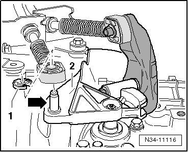
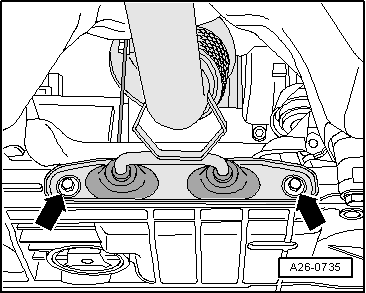
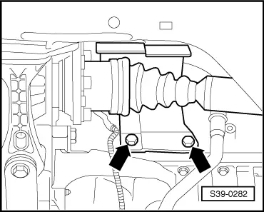
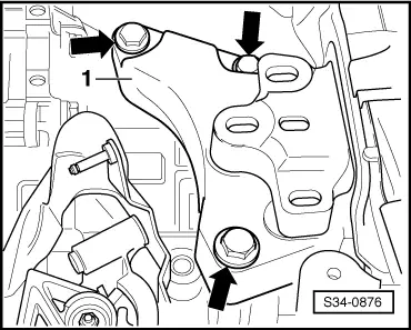
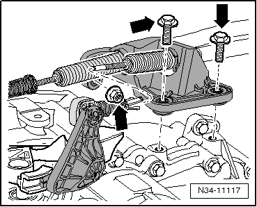
–  Disconnect cable support from gearbox -arrows-, lay aside and tie up.
  Note
t  
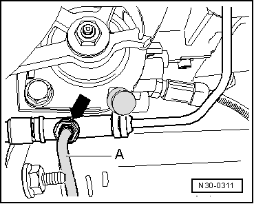
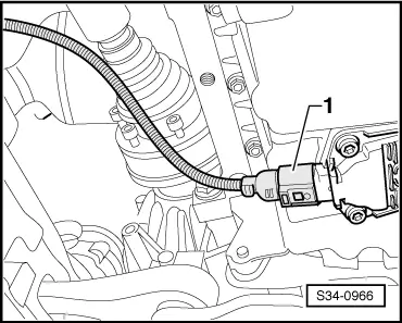
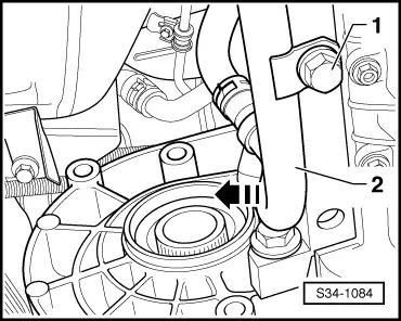
A plastic line is fitted between the master cylinder and the bleeder/slave cylinder. This plastic line must not be disconnected (do not use hose clamp -MP7–602-).
t  When performing the following work, make sure that no brake fluid comes into contact with the frame side rail or the gearbox. If this is the case, these points must be cleaned thoroughly.
To ensure that the brake fluid does not completely flow out of the clutch control, carry out the following work procedure:
  N34-11117
–  Connect the bleeder hose -A- with the drip bottle of the brake bleeding device.
–  Fit the bleeder hose -A- onto the bleeder -arrow-.
–  Open vent valve.
  Note
On certain vehicles the vent valve can be opened by hand. To do so, turn the vent valve 180° to the left as far as the stop.
–  Press the clutch pedal and leave it in this position. Do not let it return to initial position.
–  Close the vent valve and disconnect the bleeder hose -A- from the bleeder -arrow-.
  N30-0311
–  Pull out retaining clip -arrow- for plastic line -2- up to the stop.
–  Pull out the plastic line from the bleeder/slave cylinder and close with a suitable plug.
  Note
Do no longer move the clutch pedal after removing the plastic line.
–  Disconnect plug -1- from the reversing light switch -F4-.
–  Remove the connector -3- and the cable -4- from the starter.
–  Remove engine/gearbox connecting screws at the top.
–  Remove the earth strap from the front fixing screw for the gearbox console.
If hose and cable connections are located in the area of the lifting eye of the engine for the supporting device -T30099-, these must now be removed.
  S34-1223
–  Fit supporting device -T30099-.
–  Hang the spindles of the support fixture in the lifting eyes of the engine.
–  Slightly pre-tension the engine/gearbox unit via the spindles, do not raise.
–  Loosen the wheel bolts on front left and front right.
–  Raise vehicle → BookletYeti.
–  Remove wheels at the front.
–  Remove noise insulation → Body Work; Rep. gr.50 and front left and right wheelhouse liner → Body Work; Rep. gr.66.
–  Unscrew bracket from starter and remove starter → Electrical System; Rep. gr.27.
–  Remove all supports for exhaust gas system from gearbox and from exhaust pipe → Engine; Rep. gr.26.
  S34-1234
–  Separate exhaust system at the clamping sleeve and remove bracket for the exhaust system from the assembly carrier -arrows- → Engine; Rep. gr.26.
–  Tie up pre-exhaust pipe.
  Note
The decoupling elements in the exhaust pipe should not be bent by more than 10° - risk of damage.
  A26-0735
–  Remove pendulum support from gearbox, to do so release the bolts -arrow B- and -arrow C-.
  S34-0882
–  Disconnect plug -1- from oil level and oil temperature sender -G266-.
For vehicles with start-stop system
  S34-0966
–  Separate the plug from the transmission neutral sender -G701--arrow-.
Continued for all vehicles:
  N34-11322
–  Disconnect the plug connection on the front left vehicle level sensor -G78- (if present).
–  Unscrew nut -2-.
–  Release screw -1- and remove the sender.
–  Fix the assembly carrier before removing → Chassis; Rep. gr.40.
–  Remove assembly carrier with pendulum support, anti-roll bar, consoles, steering gear and track control arms → Chassis; Rep. gr.40.
  S94-0202
–  If applicable remove cap for drive shaft.
For vehicles with auxiliary heating
  S39-0282
–  Unscrew screw -1- and carefully press off the pipe -2- of the auxiliary heating from the engine -in direction of arrow-.
  Note
In this case do not open the cooling system.
Continued for all vehicles
–  Remove left and right drive shafts from the flange shafts of the gearbox → Chassis; Rep. gr.40 and tie up as far as possible (do not damage the surface protection).
For vehicles with particle filter
–  Remove particle filter with bracket for particle filter → Engine; Rep. gr.26.
For all vehicles
  S34-1084
–  Unscrew the screws -arrows- of the left unit mounting -2- from the console -1-.
  S34-0875
–  Lower the gearbox to the dimension -a- approx. 60 mm by adjusting the spindles.
  S34-0869
–  Unscrew the fixing screws -arrows- for the console -1-.
–  Remove console -1- from gearbox.
–  Remove relay lever together with cable lock → Chapter.
–  Remove the gearshift lever from the gearshift shaft.
–  Remove engine/gearbox connecting screws below.
–  Align gearbox mount -3282 - for removal of gearbox „02Q“ with adjusting plate -3282/33-.
–  Insert gearbox mount -3282- into engine/gearbox jack, e.g. -V.A.G 1383A--V.A.G 1383A-.
–  Align arms of the gearbox mount to match the holes in the adjusting plate.
  S34-0876
–  Screw in mounting elements-A-, as shown on the adjusting plate.
–  Instead of the mounting element-C- screw in the bolt -3282/29-.
–  Position the engine and gearbox jack e.g. -V.A.G 1383A- below the vehicle; the arrow -B- on the adjusting plate points in the direction of travel/vehicle.
–  Align the adjusting plate parallel to the gearbox.
  S34-0881
–  Secure adapter -MP3-419/40- in the threaded bore of the gearbox housing as shown.
–  Subsequently screw in the bolt -3282/29- into the hole for the fixing screw of the pendulum support on the gearbox.
–  Secure the gearbox on the gearbox mount -3282- using screw (M10 x 20) -A-.
While doing so the drift -B- should close at the bottom flush with the guide of the gearbox mount -3282--arrow-.
–  Remove engine/gearbox -C- connecting screw.
  S34-0827
–  Remove small cover plate -A- for flywheel.
–  Unscrew engine/gearbox connecting screw -arrow-.
–  Press gearbox from engine (dowel sleeves).
  S34-0879
–  Turn the gearbox in the area of the differential gear via the spindle -1- of the gearbox mount -3282- upwards.
–  Position the gearbox via the spindle -2- of the gearbox mount -3282- inclined to the left.
–  Carefully lower the gearbox.
  Note
Observe all lines when lowering the gearbox.
  S34-1087

Check gear oil level > < Repairing gearbox housing