
Yeti
| Connection diagram for coolant hoses |
| The engine has two independent cooling systems → self-study programme no. 68. |
| t | Engine cooling system (bright coloured components) |
| t | Charge air cooling system (dark coloured components) |
| The expansion reservoir supplies both cooling systems. |
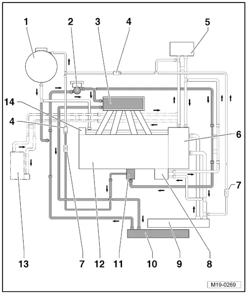
| 1 - | Expansion reservoir |
| 2 - | Coolant recirculation pump -V50- |
| q | removing and installing → Chapter |
| 3 - | Charge air cooler |
| q | in the intake manifold → Chapter |
| 4 - | Non-return valve |
| q | in the coolant hose, not visible from the outside |
| 5 - | Heat exchanger of heating system |
| 6 - | Coolant regulator housing |
| 7 - | Throttle valve |
| q | in the coolant hose, not visible from the outside |
| 8 - | Engine oil cooler |
| 9 - | Radiator |
| 10 - | Additional water cooler for charge air system |
| 11 - | Exhaust gas turbocharger |
| q | removing and installing → Chapter |
| 12 - | Cylinder head/cylinder block |
| q | fill with fresh coolant after replacing |
| 13 - | Auxiliary heating |
| q | only for vehicles with special equipment |
| 14 - | Coolant pump |
| q | removing and installing → Chapter |