Yeti
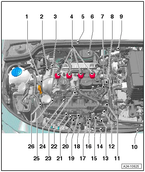
| Fitting location of the injection system |
| The components A to G are not shown on the explosion sign. |

| 1 - | Camshaft adjustment valve 1 -N205- |
| 2 - | Solenoid valve for charge pressure control -N75- |
| q | screwed onto turbocharger → Chapter |
| 3 - | Turbocharger divert air valve -N249- |
| q | screwed onto turbocharger → Chapter |
| 4 - | Ignition coils with a power output stage |
| q | removing and installing → Chapter |
| q | Ignition coil 1 with a power output stage -N70- |
| q | Ignition coil 2 with a power output stage -N127- |
| q | Ignition coil 3 with a power output stage -N291- |
| q | Ignition coil 4 with a power output stage -N292- |
| 5 - | Engine control unit -J623 - |
| q | removing and installing → Chapter |
| 6 - | Lambda probe before catalyst -G39- |
| q | in the exhaust pipe → Chapter |
| 7 - | High pressure pump |
| q | removing and installing → Chapter |
| 8 - | Control valve for fuel pressure -N276- |
| q | Part of the high pressure pump |
| 9 - | Plug for lambda probe upstream of catalytic converter -G39- |
| q | in the bracket on the partition wall |
| 10 - | Coolant temperature sender at radiator outlet -G83- |
| q | in bottom radiator fitting → Chapter |
| 11 - | Setting element for the intake manifold flap valve |
| 12 - | Intake manifold flap valve -N316- |
| 13 - | Engine speed sender -G28 - |
| q | in front cylinder block on the bottom left |
| 14 - | Charge pressure sender -G31- |
| q | screwed onto charge-air pipe for throttle valve control unit - J338- → Chapter |
| 15 - | Plug for knock sensor 1 -G61- |
| q | below the intake manifold |
| 16 - | Plug connection of Hall sender -G40- |
| q | below the intake manifold |
| 17 - | 8-pin plug connection for injection valves |
| q | below the intake manifold |
| 18 - | Throttle valve control unit -J338- |
| q | with throttle valve drive -G186-, throttle valve drive angle sender 1 -G187- and throttle valve drive angle sender 2 -G188-. |
| q | after replacing, the engine control unit must be adapted → Vehicle diagnostic, testing and information system VAS 5051 |
| q | removing and installing → Chapter |
| q | clean → Chapter |
| 19 - | Solenoid valve 1 for activated charcoal filter -N80- |
| 20 - | Intake air temperature sender - G42- |
| q | bolted to front intake manifold → Chapter |
| 21 - | Knock sensor 1 -G61- |
| q | at front cylinder block below the intake manifold |
| q | Tightening torque: 20 Nm |
| 22 - | Coolant temperature sender -G62- |
| q | in housing of coolant pump → Chapter |
| q | replace → Chapter |
| 23 - | Hall sender -G40- |
| q | screwed onto the front cylinder head cover → Chapter |
| 24 - | Fuel pressure sender -G247 - |
| q | in the fuel distributor → Chapter |
| q | removing and installing → Chapter |
| 25 - | Potentiometer for intake manifold flap -G336- |
| q | in the right intake manifold |
| 26 - | Oil pressure switch -F22- |
| q | 0.215 - 0.295 MPa (2.15 - 2.95 bar) blue |
| q | in the bracket for auxiliary units → Chapter |
| q | check → Chapter |
| A - | Oil pressure switch for reduced oil pressure -F378- |
| q | check → Chapter |
| B - | Valve for oil pressure control -N428 - |
| q | in upper part of oil pan → Chapter |
| C - | Air mass meter -G70- and intake air temperature sender 2 -G299- |
| q | behind the air filter → Chapter |
| D - | lambda probe downstream of catalytic converter -G130- |
| q | in the exhaust pipe → Chapter |
| E - | Accelerator pedal position sender - G79- and accelerator pedal position sender 2 -G185- |
| q | in the vehicle interior |
| q | removing and installing → Chapter |
| F - | Radiator fan control unit -J293- |
| q | integrated into the radiator fan -V7- |
| G - | Injection valves |
| q | Injection valve for cylinder 1 -N30- |
| q | Injection valve for cylinder 2 -N31- |
| q | Injection valve for cylinder 3 -N32- |
| q | Injection valve for cylinder 4 -N33- |
| q | in the fuel distributor → Chapter |
| q | removing and installing → Chapter |
