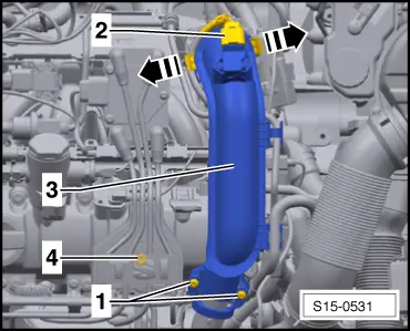
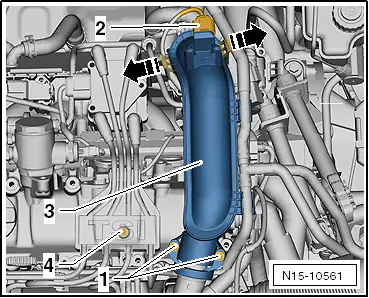
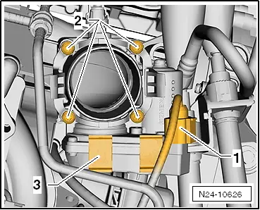
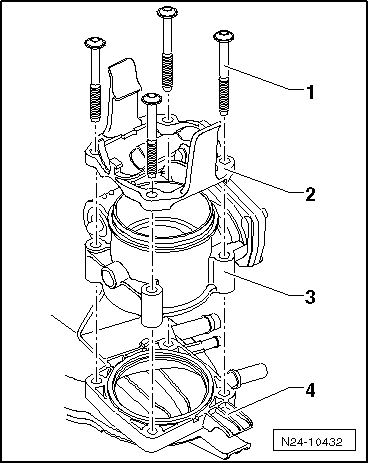
Removing and installing the throttle valve control unit for Yeti Power Unit
 Note
Note
|
|
|
|
|
|
|
|
|
Note
|
|
|
|
|
|

Note
|
|
|
|
|
|
|
|
|
Note
|
|
|
|
|
|