
Yeti
| Connection diagram for vacuum hoses |
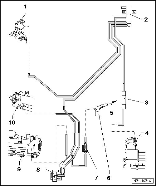
| 1 - | Vacuum setting element |
| q | at exhaust gas turbocharger |
| q | with position sender for charge pressure regulator -G581- |
| 2 - | Solenoid valve for charge pressure control -N75- |
| 3 - | Silencer |
| 4 - | Air filter housing |
| 5 - | To the brake servo unit |
| 6 - | Connecting piece |
| q | at the vacuum pump |
| 7 - | Non-return valve |
| q | Check fitting position |
| 8 - | Changeover valve for radiator of exhaust gas recirculation -N345- |
| q | Check change-over → Chapter |
| 9 - | Vacuum unit |
| q | in the cylinder head cover |
| 10 - | Vacuum setting element |
| q | for changeover of radiator for exhaust gas recirculation |