skoda Workshop Repair Guides

Skoda Workshop Service and Repair Manuals

Fuel preparation system Diesel injection > < Charge-air system - radiator, leaktightness
Inspect the vacuum system
  Caution
When routing the vacuum lines, make sure that the lines are not kinked, twisted or crimped. Otherwise this can lead to breakdown.
Special tools and workshop equipment required
t  Hand vacuum pump, e.g. -VAS 6213-
–  Remove engine cover → Chapter.
Check vacuum supply line, vacuum reservoir and non-return valve
–  Unclip the changeover valve for radiator of exhaust gas recirculation -N345- from the front bracket at the intake manifold.
   
–  Detach the vacuum hose on the bottom connection of the exhaust gas recirculation radiator change-over valve -N345--arrow in I-.
–  Detach the vacuum hose on the bottom connection of the charge pressure control solenoid valve -N75--arrow in II-.
–  Close off the open hose ends with suitable plugs.
  Note
Do not use any thread screws or thread bolts.
  N21-10206
–  Detach the vacuum hose -arrow in l- on the connecting piece of the vaccum pump.
  Note
  N21-10207
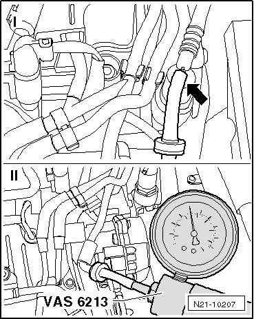
In order to generate „vacuum“, push the ring -1- for the hand vacuum pump -VAS 6213- into position -A-.
–  Attach the hand vacuum pump -VAS 6213- to the detached hose and generate a vacuum of 0.06 MPa (0.6 bar).
–  Observe the pressure gauge of the hand vacuum pump for approx. 30 seconds.
l  The vacuum must not drop.
If the vacuum drops:
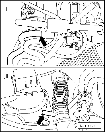
–  Search for damage, for example a leaky connection in the hose line, and replace the corresponding part.
If the vacuum does not drop:
–  First of all, detach the hose at the hand vacuum pump -VAS 6213-.
–  Remove one of the plugs from the hose ends.
If the non-return valve is functional, a significant spluttering can now be heard when the pressure is compensated for in the vacuum reservoir.
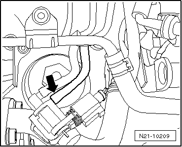
If no spluttering can be heard:
–  Replace non-return valve.
–  Re-connect all vacuum hoses.
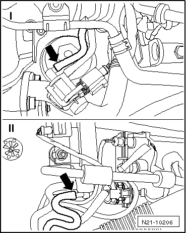
Check the control vacuum line to the exhaust turbocharger
  N24-10282
–  Detach the hose -arrow in I- from the middle connection of the charge pressure control solenoid valve -N75-.
–  Detach the hose from the vacuum setting element of the exhaust turbocharger -arrow in II-.
–  Close one opening of the hose with a suitable plug.
  Note
Do not use any thread screws or thread bolts.
–  Attach the hand vacuum pump -VAS 6213- to the other end of the hose and generate a vacuum of 0.06 MPa (0.6 bar).
–  Observe the pressure gauge of the hand vacuum pump for approx. 30 seconds.
l  The vacuum must not drop.
If the vacuum drops:
–  Replace vacuum hose.
Check the control vacuum line to the vacuum setting element for the change-over flap for radiator of exhaust gas recirculation
  N21-10208
–  Detach the hose on the middle connection of the exhaust gas recirculation radiator change-over valve -N345--arrow-.
–  Attach the hand vacuum pump -VAS 6213- to the detached hose and generate a vacuum of 0.06 MPa (0.6 bar).
–  Observe the pressure gauge of the hand vacuum pump for approx. 30 seconds.
l  The vacuum must not drop.
If the pressure drops:
–  Detach the vacuum hose on the vacuum setting element for the change-over flap for radiator of exhaust gas recirculation.
–  Attach the hand vacuum pump -VAS 6213- with the factory-delivered test hose (included in the scope of delivery) to the vacuum setting element and generate a vacuum of 0.06 MPa (0.6 bar).
  Note
t  The adjustment on the vacuum setting element must be noticeable and the vacuum must not drop. If this is not the case, replace the radiator for exhaust gas recirculation → Chapter.
t  If no defect can be found on the vacuum setting element, replace the vacuum line of the changeover valve for radiator of exhaust gas recirculation -N345-.
  N21-10209

Fuel preparation system Diesel injection > < Charge-air system - radiator, leaktightness