
XT-6 2WD L6-2.7L SOHC (1989)
2.
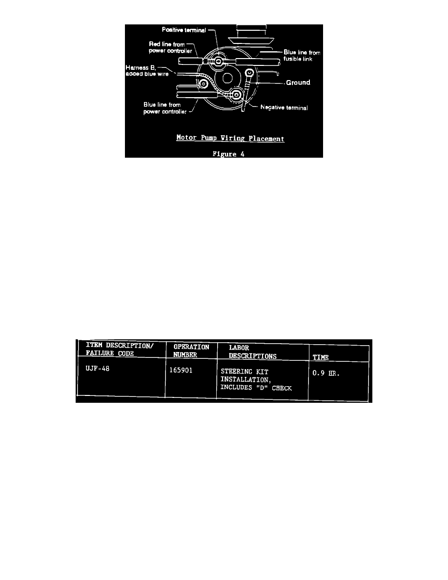
Remove the existing power controller. Note proper wire placement and orientation. To install new power controller, first insert the eye hook
terminal of harness "B" through the rubber protector/insulator on the blue line from the new power controller and secure both to the negative
terminal of the motor pump. See Figure 4.
3.
Fasten remaining wire terminals to complete installation of the new power controller. Ensure all previously removed terminals are refastened
tightly and correctly.
4.
Run harness "B" behind wiper motor and existing harness towards the left hand strut tower. Mate harness "B" with F62 of the vehicle's wiring
harness. When harness "B" is properly positioned, secure with vinyl tape every 2-4 inches as necessary.
5.
Reconnect battery cable.
6.
Using the diagnosis connector (Figure 2), perform a D-check as outlined on the diagnosis access information page.
7.
After completing D-check, reinstall trim panel.
8.
Test drive vehicle.
A diagnostic supplement will be released shortly providing full details on interpreting trouble codes and confirming component operation. Until then,
additional information on diagnosis is available through the SOA Tech Helpline.
Diagnosis Access Information
READ MEMORY
1.
Ignition OFF.
2.
Connect 1, black, to 4, yellow of diagnosis connector.
3.
Ignition ON, (Engine OFF).
4.
Lamp ON then OFF.
5.
Disconnect 1 from 4 of diagnosis connector.
6.
Read code.
D-CHECK
1.
Ignition OFF.
2.
Connect 3, black, to 5, green, of diagnosis connector.
3.
Ignition ON, Engine OFF.
4.
Lamp blinks ON/OFF/ON/OFF etc. in normal .6 second time intervals.