
XT-6 2WD L6-2.7L SOHC (1989)
3.
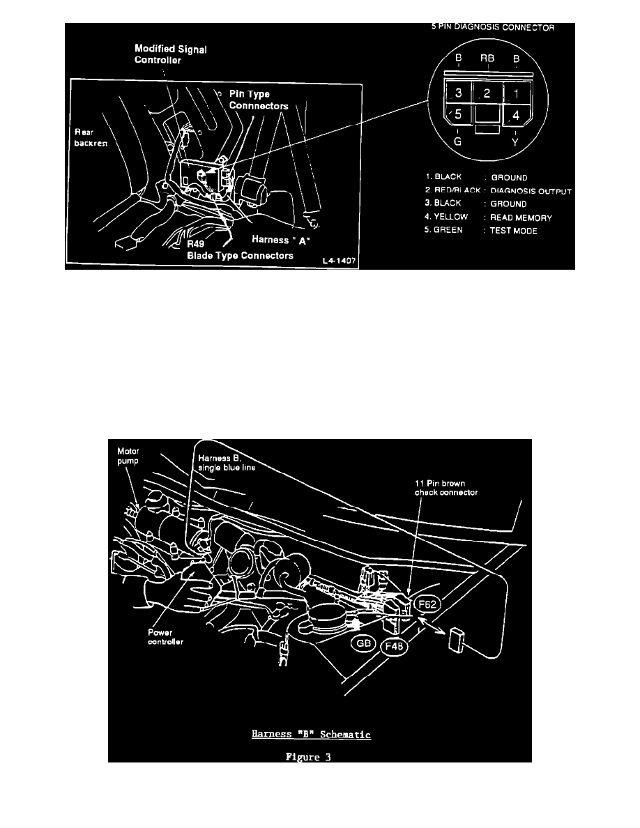
Remove the existing signal controller and replace with the modified unit. Note that harness "A" has several connectors. One of these is a 5 pin
diagnostic connector that can be used for accessing diagnostic information. This connector doesn't get plugged into anything. The multi-pin blade
type connector mates with OEM harness connector R49. The remaining pin type connectors should already be plugged into the modified signal
controller. See Figure 2.
Modified Signal Controller
4.
Route the wiring below the signal controller. Avoid pinching or contact with sharp objects, using vinyl tape to secure as necessary.
Note:
Leave trim off for access to diagnosis connector. D-check must be performed after the installation.
Installation of Power Controller and Harness "B"
1.
Before beginning, ensure the battery is still disconnected. Harness "B" is installed under the hood between the negative terminal on the motor
pump and 11 pin brown check connector F62 located near the left strut tower. See Figure 3.