|
Camshaft, Remove and Install
 Remove Remove
Remove air cleaner housing and got film mass air flow meter and
air intake hose - see illustration "Air duct X 20 DTL, Y 20 DTL"
and "Air duct Y 20 DTH up to MY 2003" and "Air duct Y 20 DTH as of
MY 2003, Y 22 DTR".
Remove cylinder head cover – see operation "Cylinder Head
Cover, Remove and Install".
Remove vacuum pump from cylinder head and lay aside to rear
– see operation "Vacuum Pump, Remove and Install".
Remove ribbed V-belt tensioner – see operation "Ribbed
V-belt Tensioner Assembly, Remove and Install".
Lock engine at 1st cylinder TDC – see operation "Engine,
Lock at 1st Cylinder TDC (Timing, Check)".
|
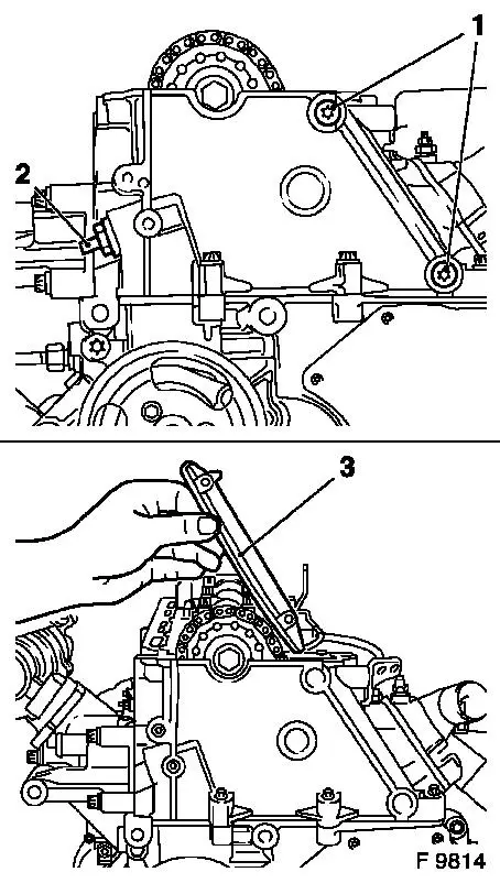
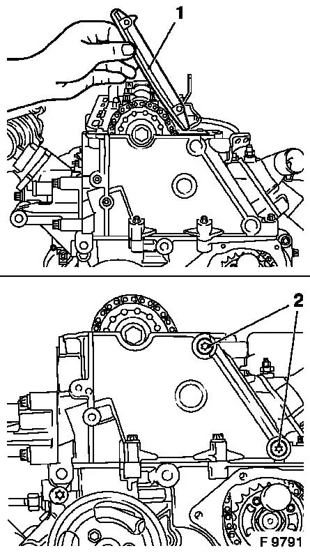
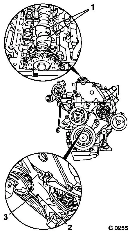
Remove simplex chain tensioner (2) – note installation
position.
Caution
Use sheet metal plate or suitable heat shielding to avoid
damaging the guide rails.
Remove
Heat fastening bolts (1) intensively with hot air blower and
remove. Remove simplex timing chain guide rail (3) upwards –
note installation position.
Clean thread for the fastening bolts (1) in cylinder head.
|
|
Caution
|
Remove Test Gauge KM-932 from cylinder head and Injection Pump
Lock Pin KM-927 from lock bore.
Remove
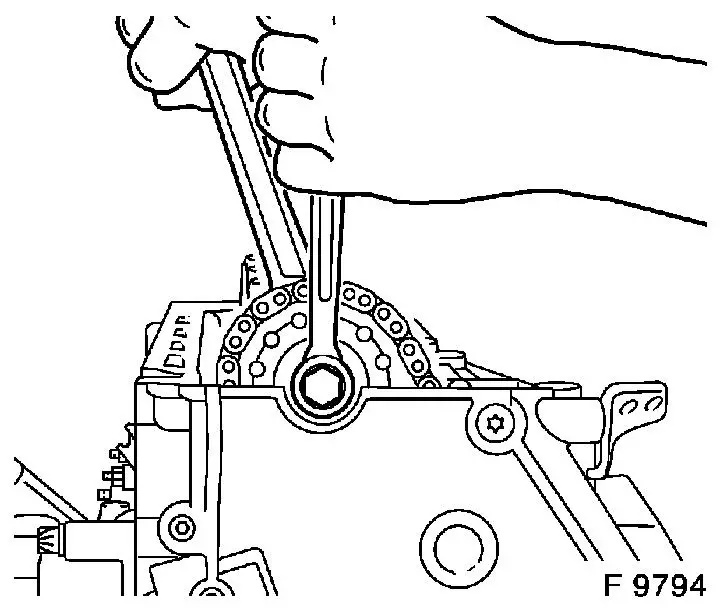
Remove camshaft sprocket from camshaft – counterhold with
open-ended wrench on hex of camshaft.
Note: To simplify
installation, suspend simplex timing chain at suitable point.
|
|
Caution
|
Note marking before dismantling camshaft bearing cover!
The camshaft must release evenly from the bearing seats.
Remove
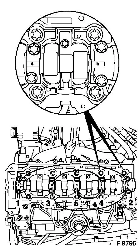
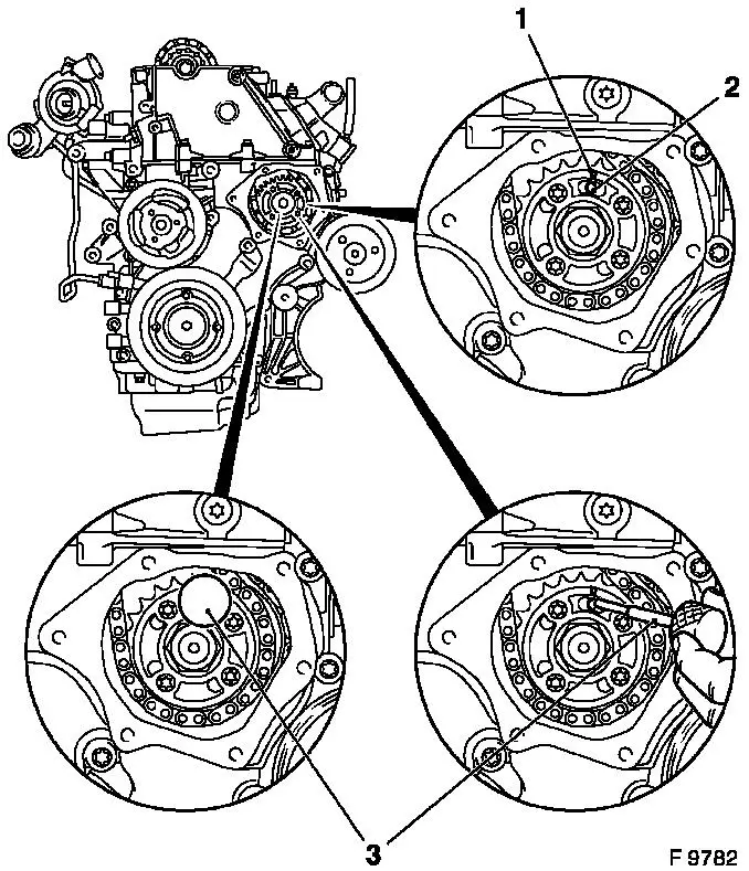
Release camshaft bearing cover in spiral pattern in steps of 1/2
to 1 turn in sequence illustrated.
Detach camshaft bearing caps from cylinder head and remove
camshaft.
Note: If the camshaft
is being replaced, the valve bridges must also be replaced –
note installation positions of valve bridges!
|
|
 Clean Clean
Clean sealing surfaces and remove gasket residues.
 Inspect
Check camshaft and bearing seat for wear, replace if
necessary.
|
 Install
If valve bridges are being replaced – note installation
position. Marks on the valve bridges are on the injection nozzle
traverse side.
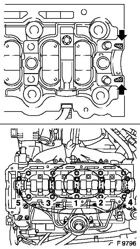
Apply surface sealant (green) to sealing surfaces (arrows).
Coat sliding surfaces of valve bridges and camshaft with MoS
2 lubricating paste (grey). Insert camshaft
into cylinder head.
Caution
Note identification on camshaft bearing caps.
Install
Attach camshaft bearing caps to cylinder head and tighten using
spiral pattern in steps of 1/2 up to 1 turn in sequence illustrated
– tightening torque 15 Nm / 11 lbf. ft.
|
|
Insert camshaft sprocket in simplex timing chain.
Attach camshaft sprocket with new fastening bolt to camshaft and
tighten by hand.
Caution
Ensure that the camshaft sprocket is not askew on the camshaft
– camshaft sprocket must lie plane on the camshaft.
Install
|
Insert and install simplex timing chain guide rail (1) –
use new fastening bolts (2) – note installation position
– tightening torque 8 Nm / 6 lbf. ft.
|
|
Inspect
|
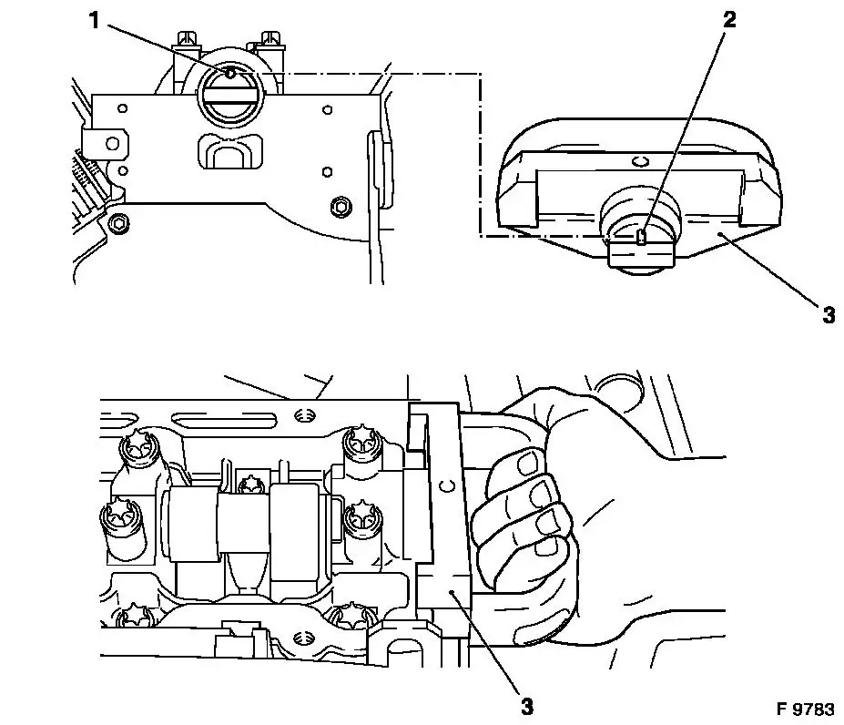
Arrow (1) on simplex fuel injection pump sprocket must align
with recess in fuel injection pump flange and lock bore (2) in fuel
injection pump.
Install
Insert Injection Pump Lock Pin KM-927 (3) in lock bore of fuel
injection pump.
|
|
|
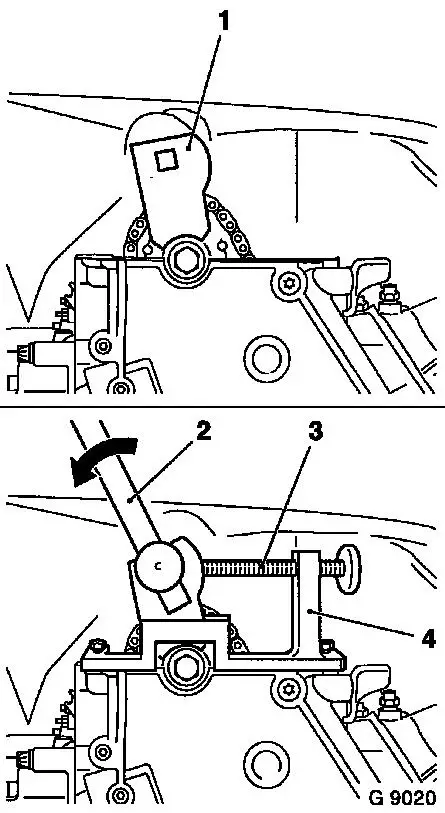
Insert carrier (1) of Adjuster KM-933 (4) vertically into
camshaft sprocket.
Install Adjuster KM-933 on cylinder head.
 Adjust Adjust
Use handle (2) to exert slight pressure on the carrier in the
direction of arrow (counter engine rotational direction) and fix in
place with holder bolt (3).
Injection Pump Lock Pin KM-927 must be able to be installed and
removed under suction. If this is not the case, decrease the
pressure on the carrier disk slightly via the holder bolt.
|
|
Install
Fasten camshaft sprocket to camshaft – tightening torque
90 Nm / 66 lbf. ft. + 60° + 30°.
|
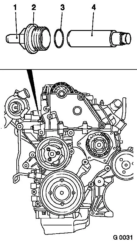
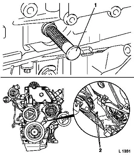
Insert Simplex chain tensioner (4) into cylinder head –
closed side of chain tensioner must point to tensioner blade.
Install Simplex chain tensioner screw plug (2) with new seal ring
(3) – tightening torque 60 Nm / 44 lbf. ft.
Caution
A distinction must be made between versions with and without
release bolts (1).
In versions with release bolts the chain tensioner must be
untightened using the release bolt after installation!
Inspect
Press in the release pin with a hammer shaft until a click is
heard.
It must be possible to push in release bolt up to stop with
thumb and for it to slide back to its original position
automatically – the release bolt can no longer be pushed in
once the oil pressure has built up.
|
|
Remove
Remove all locking and adjusting tools.
Adjust
|
At fastening bolt of torsional vibration damper, turn crankshaft
two turns (approx. 720°) in engine rotational direction to just
before "1st cylinder TDC" – mark (3) on torsional vibration
damper is just before lug (2) on timing case.
Inspect
In this position, the cams (1) of the 1st cylinder are just
before TDC (both cams point upwards).
|
|
Install
|
Insert Crankshaft Lock Pin KM-929 (1) in aperture for crankshaft
pulse pick-up and simultaneously slowly turn crankshaft further in
engine rotational direction at fastening bolt of torsional
vibration damper until crankshaft lock pin engages to stop in
cylinder block or crank web.
Inspect
In this position, marks (2) must align.
|
|
|
Arrow (1) on simplex fuel injection pump sprocket must align
with recess in fuel injection pump flange and lock bore (2) in fuel
injection pump.
Install
Insert Injection Pump Lock Pin KM-927 (3) in lock bore of fuel
injection pump.
|
|
|
Apply Test Gauge KM-932 (3) to cylinder head – pin (2)
must engage in bore (1) of camshaft.
|
|
Remove
Remove all locking tools.
Clean
Clean sealing surfaces on timing case cover and timing case
– cover aperture in timing case with lint-free cloth.
|
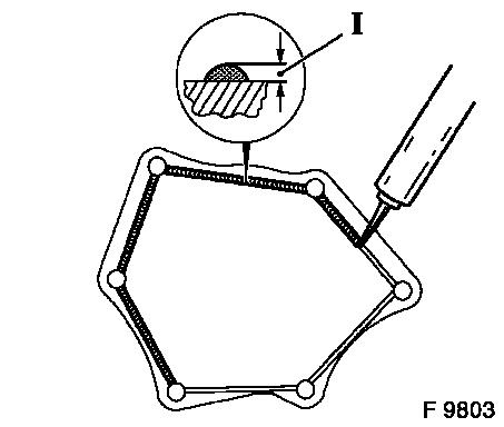
Install
Apply an approx. 2 mm (Dimension I) thick bead of silicone
sealing compound (grey) to timing case cover. Attach timing case
cover to timing case with new fastening bolts – secure using
2 threaded bolts (M6) – tightening torque 6 Nm / 4.5 lbf.
ft.
Caution
The silicone sealing compound (grey) must be applied and the
timing case must be installed (including torque checking) within 10
minutes.
|
|
Install
Attach upper coolant hose to thermostat housing and
radiator.
Attach crankshaft pulse pick-up to cylinder block with new
O-ring – tightening torque 8 Nm / 6 lbf. ft.
Attach coolant pipe to cylinder block.
Install ribbed V-belt tensioner – see operation "Ribbed
V-belt Tensioner Assembly, Remove and Install".
Install vacuum pump – see operation "Vacuum Pump, Remove
and Install".
Install cylinder head cover – see operation "Cylinder Head
Cover, Remove and Install".
Install air cleaner housing with hot film mass air flow meter
and air intake hose - see illustration "Air duct X 20 DTL, Y 20
DTL" and "Air duct Y 20 DTH up to MY 2003" and "Air duct Y 20 DTH
as of MY 2003, Y 22 DTR".
Close coolant drain bolt.
Inspect
Charge cooling system – see operations "Cooling System,
Charge and Bleed" and "Cooling System, Check for Leaks".
|
