|
Engine, Lock at 1st Cylinder TDC (Timing,
Check)
 Remove Remove
Open coolant drain bolt – collect escaping coolant.
Remove air cleaner housing with hot film mass air flow meter and
air intake hose - see illustration "Air duct X 20 DTL, Y 20 DTL"
and "Air duct Y 20 DTH up to MY 2003" and "Air duct Y 20 DTH as of
MY 2003, Y 22 DTR".
Remove cylinder head cover – see operation "Cylinder Head
Cover, Remove and Install".
Remove vacuum pump from cylinder head and lay aside to rear
– see operation "Vacuum Pump, Remove and Install".
Remove ribbed V-belt tensioner – see operation "Ribbed
V-belt Tensioner Assembly, Remove and Install".
Detach and remove upper coolant hose from thermostat housing and
radiator.
Remove
|
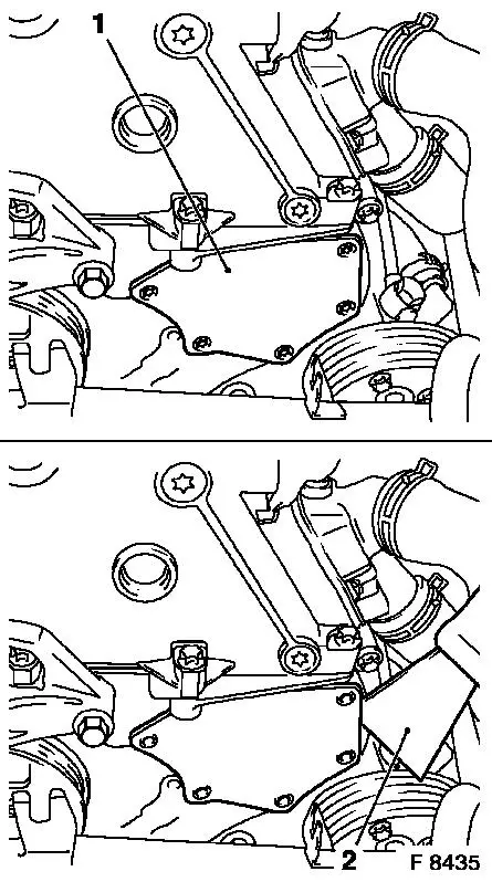
Remove fastening bolts from timing case cover (1) and carefully
separate timing case cover from timing case with a wide, flat
spatula (2).
|
|
Caution
The timing case cover must not be levered off or separated from
the timing case by force; this would lead to permanent deformity
and leaks.
 Adjust Adjust
|
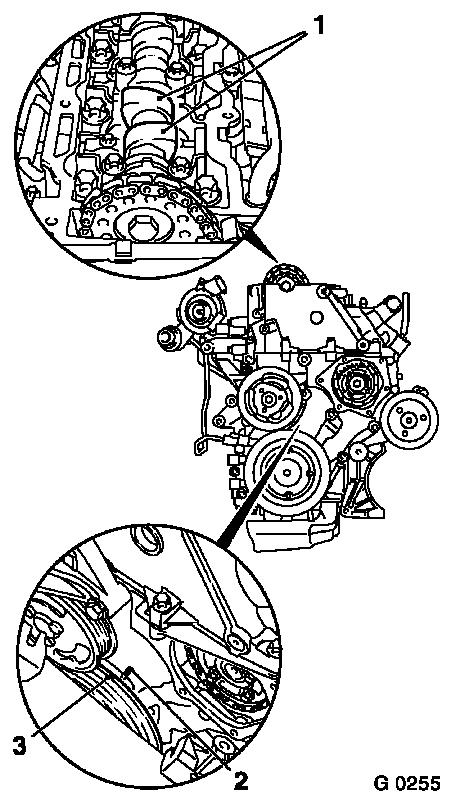
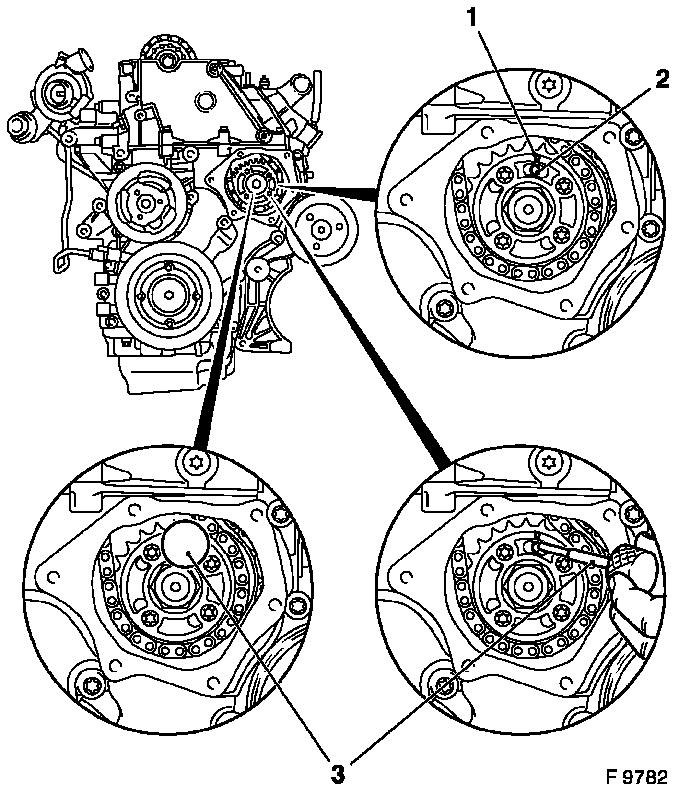
At the fastening bolt of the torsional vibration damper, turn
the crankshaft in engine rotational direction until just before
"1st cylinder TDC" – mark (3) on the torsional vibration
damper is just in front of the lug (2) on the timing case.
 Inspect
In this position, the cams (1) of the 1st cylinder are just
before TDC (both cams point upwards).
|
|
Remove
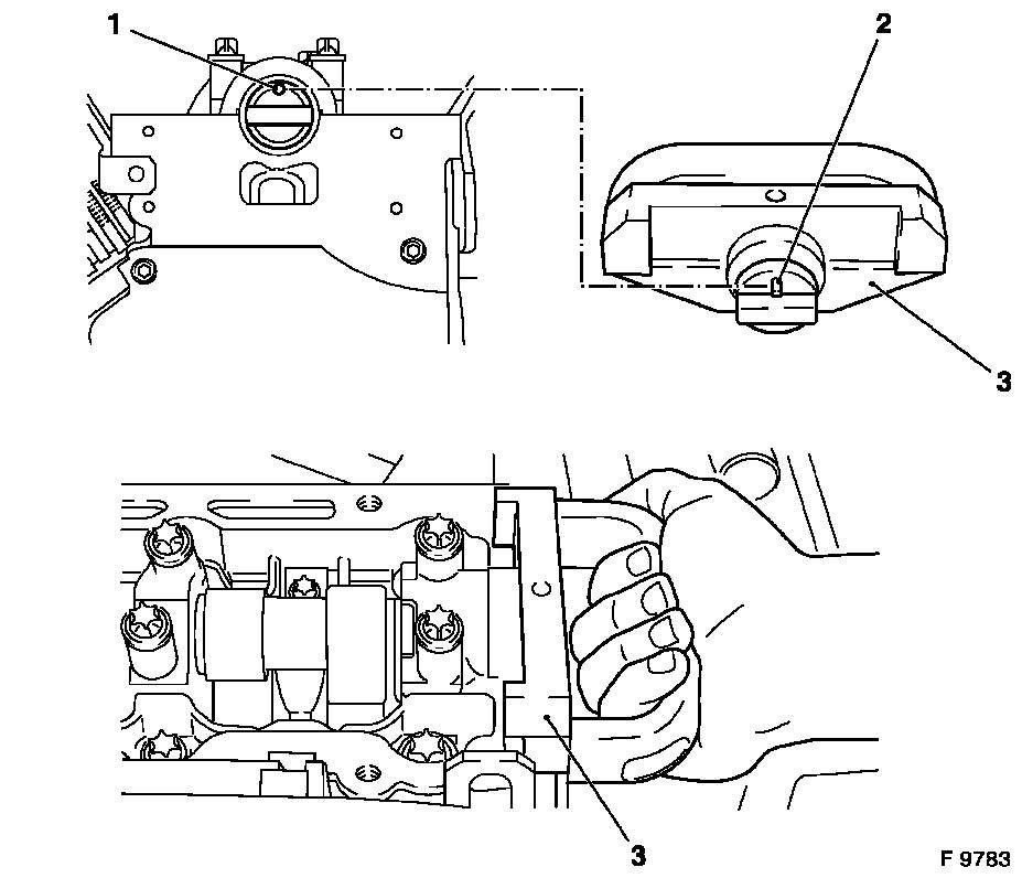
Detach wiring harness plug from dynamic oil level control and
oil temperature sensor.
|
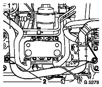
Remove fastening bolts from coolant pipe (2) and carefully press
coolant pipe (1) forwards.
|
|
Remove
|
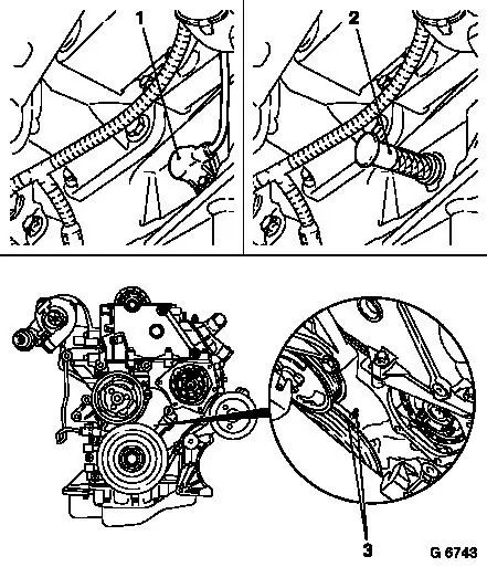
Remove crankshaft pulse pick-up (1) with O-ring from cylinder
block.
 Install
Insert Crankshaft Lock Pin KM-929 (2) in aperture for crankshaft
pulse pick-up and simultaneously slowly turn the crankshaft in
engine rotational direction at the fastening bolt of the torsional
vibration damper until the crankshaft lock pin engages to stop in
the cylinder block or crank web.
Inspect
In this position, the marks (3) must align.
|
|
Inspect
|
Arrow (1) on simplex fuel injection pump sprocket must align
with recess in fuel injection pump flange and lock bore (2) in fuel
injection pump.
Install
Insert Injection Pump Lock Pin KM-927 (3) in lock bore of fuel
injection pump.
Note: If the lock pin
cannot be inserted, carry out basic adjustment of timing –
see operation "Timing, Adjust".
|
|
Install
|
Apply Test Gauge KM-932 (3) to cylinder head – pin (2)
must engage in bore (1) of camshaft.
Note: If the test
gauge cannot be applied, carry out basic adjustment of timing
– see operation "Timing, Adjust".
|
|
Remove
Remove all locking tools.
 Clean Clean
Clean sealing surfaces on timing case cover and timing case
– cover aperture in timing case with lint-free cloth.
|
Install
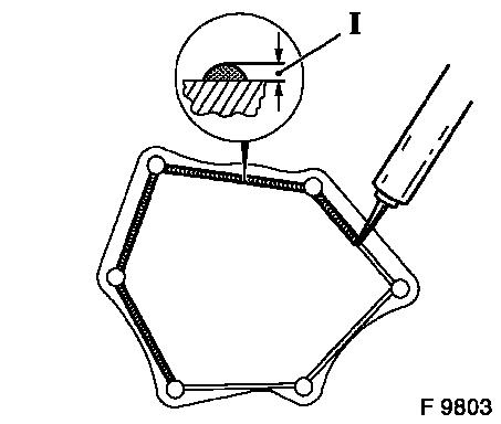
Apply an approx. 2 mm (Dimension I) thick bead of silicone
sealing compound (grey) to cover.
Attach timing case cover to timing case with new fastening bolts
– secure using 2 threaded bolts (M6) – tightening
torque 6 Nm / 4.5 lbf. ft.
Caution
The silicone sealing compound (grey) must be applied and the
timing case must be installed (including torque checking) within 10
minutes.
|
|
Install
Attach upper coolant hose to thermostat housing and
radiator.
Attach crankshaft pulse pick-up to cylinder block with new
O-ring – tightening torque 8 Nm / 6 lbf. ft.
Connect wiring harness plugs to dynamic oil level control and
oil temperature sensor.
Attach fastening bolts to coolant pipe
Install ribbed V-belt tensioner – see operation "Ribbed
V-belt Tensioner Assembly, Remove and Install".
Install vacuum pump – see operation "Vacuum Pump, Remove
and Install".
Install cylinder head cover – see operation "Cylinder Head
Cover, Remove and Install".
Install air cleaner housing with hot film mass air flow meter
and air intake hose - see illustration "Air duct X 20 DTL, Y 20
DTL" and "Air duct Y 20 DTH up to MY 2003" and "Air duct Y 20 DTH
as of MY 2003, Y 22 DTR".
Close coolant drain bolt.
Inspect
Charge cooling system – see operations "Cooling System,
Charge and Bleed" and "Cooling System, Check for Leaks".
|
