|
Timing, Adjust
Option 1: Injection pump retaining pin cannot be
inserted.
Note: Crankshaft is
locked at "1st cylinder TDC" with Lock Pin KM-929.
 Remove Remove
|
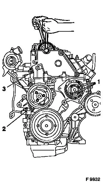
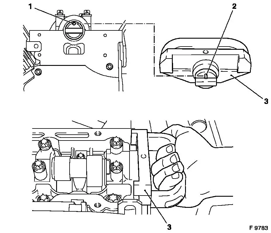
Remove simplex chain tensioner (3) and duplex chain tensioner
(2) – note installation position. Remove fastening bolt for
camshaft sprocket from camshaft – counterhold with open-ended
wrench on hex of camshaft.
 Install
Insert new bolt for camshaft sprocket and tighten hand-tight
– ensure that the camshaft sprocket is not tilted on the
camshaft. Camshaft sprocket must lie plane on the camshaft.
Remove
Remove fastening bolts (1) and loosely screw in new fastening
bolts (ensure that bolt strength is 10.9) - 5 fastening bolts for Y
20 DTH as of MY 2003 and Y 22 DTR.
|
|
 Adjust Adjust
|
Turn fuel injection pump sprocket until arrow (1) on simplex
fuel injection pump sprocket aligns with recess in fuel injection
pump flange and lock bore (2) in fuel injection pump.
Install
Insert Injection Pump Lock Pin KM-927 (3) to stop in lock bore
fuel injection pump.
|
|
|
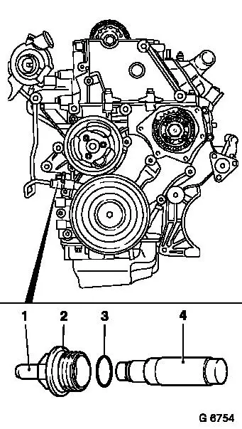
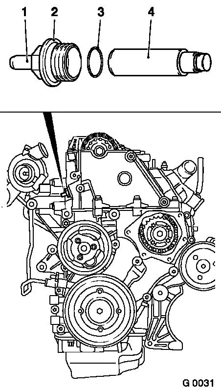
Insert Duplex chain tensioner (4) into timing case –
closed side of chain tensioner must point to tensioner blade.
Install Duplex chain tensioner screw plug (2) with new seal ring
(3) – tightening torque 60 Nm / 44 lbf. ft.
Caution
A distinction must be made between versions with and without
release bolts (1). In versions with release bolts the chain
tensioner must be untightened using the release bolt after
installation!
 Inspect
Press in the release pin with a hammer shaft until a click is
heard.
It must be possible to push in release bolt up to stop with
thumb and for it to slide back to its original position
automatically – the release bolt can no longer be pushed in
once the oil pressure has built up.
|
|
Remove Injection Pump Lock Pin KM-927.
Install
|
Tighten fastening bolts (1) with bolt strength of 10.9 for
Simplex injection pump wheel (tightening torque 28 Nm / 20.6 lbf.
ft.) - 5 fastening bolts for Y 20 DTH as of MY 2003 and Y 22
DTR.
Insert Injection Pump Lock Pin KM-927 into fuel injection pump
lock bore again.
|
|
|
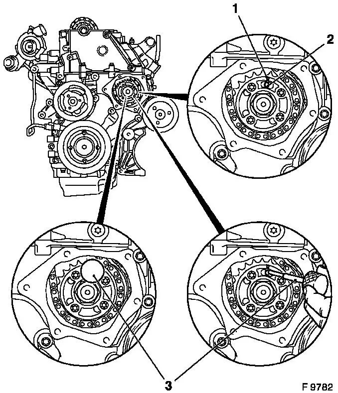
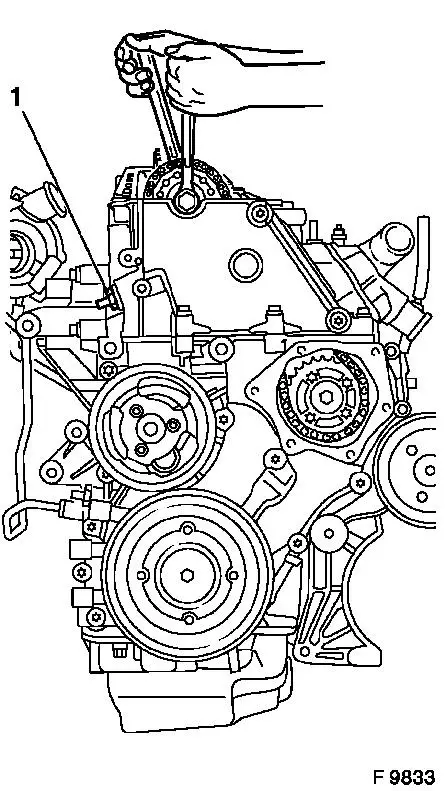
Apply Test Gauge KM-932 (3) to cylinder head – pin (2)
must engage in bore (1) of camshaft – if necessary, turn
camshaft at hex (short path).
Caution
Turn camshaft carefully and smoothly.
|
|
Install
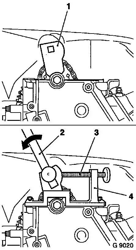
|
Insert carrier (1) of Adjuster KM-933 (4) vertically into
camshaft sprocket. Install Adjuster KM-933 on cylinder head.
Adjust
Use handle (2) to exert slight pressure on the carrier in the
direction of arrow (counter engine rotational direction) and fix in
place with holder bolt (3).
Injection Pump Lock Pin KM-927 must be able to be installed and
removed under suction. If this is not the case, decrease the
pressure on the carrier disk slightly via the holder bolt.
|
|
Install
Fasten camshaft sprocket to camshaft – tightening torque
90 Nm / 66 lbf. ft. + 60° + 30°.
|
Insert Simplex chain tensioner (4) into cylinder head –
closed side of chain tensioner must point to tensioner blade.
Install Simplex chain tensioner screw plug (2) with new seal ring
(3) – tightening torque 60 Nm / 44 lbf. ft.
Caution
A distinction must be made between versions with and without
release bolts (1). In versions with release bolts the chain
tensioner must be untightened using the release bolt after
installation!
Inspect
Press in the release pin with a hammer shaft until a click is
heard.
It must be possible to push in release bolt up to stop with
thumb and for it to slide back to its original position
automatically – the release bolt can no longer be pushed in
once the oil pressure has built up.
|
|
Remove
Remove all locking and adjusting tools.
|
Adjust
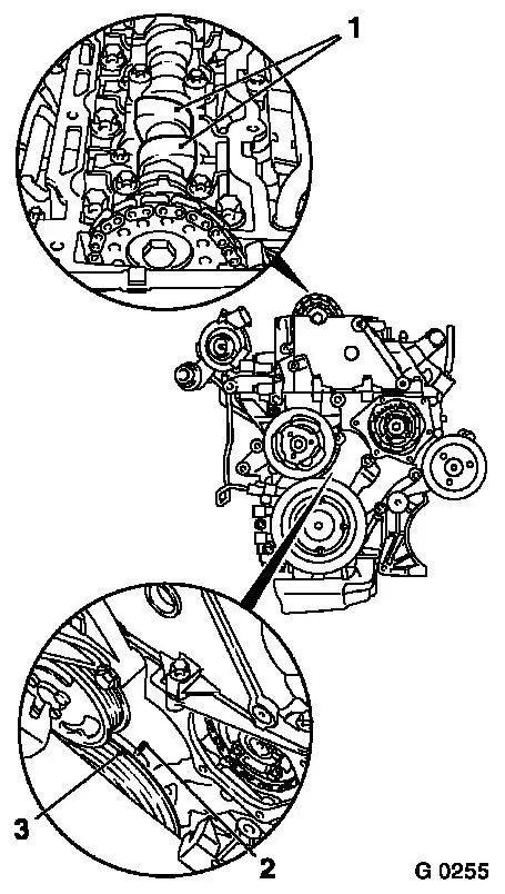
At fastening bolt of torsional vibration damper, turn crankshaft
two turns (approx. 720°) in engine rotational direction to just
before "1st cylinder TDC" – mark (3) on torsional vibration
damper is just before lug (2) on timing case.
Inspect
In this position, the cams (1) of the 1st cylinder are just
before TDC (both cams point upwards).
|
|
Install
|
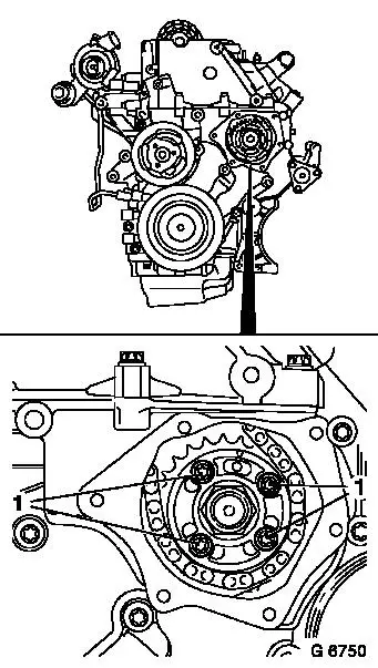
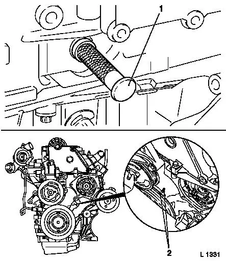
Insert Crankshaft Lock Pin KM-929 (1) in aperture for crankshaft
pulse pick-up and simultaneously slowly turn crankshaft further in
engine rotational direction at fastening bolt of torsional
vibration damper until crankshaft lock pin engages to stop in
cylinder block or crank web.
Inspect
In this position, marks (2) must align.
|
|
|
Arrow (1) on simplex fuel injection pump sprocket must align
with recess in fuel injection pump flange and lock bore (2) in fuel
injection pump.
Install
Insert Injection Pump Lock Pin KM-927 (3) in lock bore of fuel
injection pump.
|
|
|
Apply Test Gauge KM-932 (3) to cylinder head – pin (2)
must engage in bore (1) of camshaft.
|
|
Remove
Remove all locking tools.
Install
Install removed components – see operation "Engine, Lock
at 1st Cylinder TDC (Timing, Check)".
Option 2: Camshaft test gauge cannot be inserted
in cylinder head.
Note: Crankshaft is
locked at "1st cylinder TDC" with Lock Pin KM-929 and fuel
injection pump with Lock Pin KM-927.
Remove
Remove Injection Pump Lock Pin KM-927.
|
Remove simplex chain tensioner (1) – note installation
position.
Remove fastening bolt for camshaft sprocket from camshaft
– counterhold with open-ended wrench on hex of camshaft.
Install
Insert new bolt for camshaft sprocket and tighten hand-tight
– ensure that the camshaft sprocket is not tilted on the
camshaft. Camshaft sprocket must lie plane on the camshaft.
|
|
Inspect
|
Arrow (1) on simplex fuel injection pump sprocket must align
with recess in fuel injection pump flange and lock bore (2) in fuel
injection pump.
Install
Insert Injection Pump Lock Pin KM-927 (3) in lock bore of fuel
injection pump.
|
|
|
Apply Test Gauge KM-932 (3) to cylinder head – pin (2)
must engage in bore (1) of camshaft – if necessary, turn
camshaft at hex (short path).
Caution
Turn camshaft carefully and smoothly.
|
|
Install
|
Insert carrier (1) of Adjuster KM-933 (4) vertically into
camshaft sprocket. Install Adjuster KM-933 on cylinder head.
Adjust
Use handle (2) to exert slight pressure on the carrier in the
direction of arrow (counter engine rotational direction) and fix in
place with holder bolt (3).
Injection Pump Lock Pin KM-927 must be able to be installed and
removed under suction. If this is not the case, decrease the
pressure on the carrier disk slightly via the holder bolt.
|
|
Install
Fasten camshaft sprocket to camshaft – tightening torque
90 Nm / 66 lbf. ft. + 60° + 30°.
|
Insert Simplex chain tensioner (4) into cylinder head –
closed side of chain tensioner must point to tensioner blade.
Install Simplex chain tensioner screw plug (2) with new seal ring
(3) – tightening torque 60 Nm / 44 lbf. ft.
Caution
A distinction must be made between versions with and without
release bolts (1). In versions with release bolts the chain
tensioner must be untightened using the release bolt after
installation!
Inspect
Press in the release pin with a hammer shaft until a click is
heard.
It must be possible to push in release bolt up to stop with
thumb and for it to slide back to its original position
automatically – the release bolt can no longer be pushed in
once the oil pressure has built up.
|
|
Remove
Remove all locking and adjusting tools.
|
Adjust
At fastening bolt of torsional vibration damper, turn crankshaft
two turns (approx. 720°) in engine rotational direction to just
before "1st cylinder TDC" – mark (3) on torsional vibration
damper is just before lug (2) on timing case.
Inspect
In this position, the cams (1) of the 1st cylinder are just
before TDC (both cams point upwards).
|
|
Install
|
Insert Crankshaft Lock Pin KM-929 (1) in aperture for crankshaft
pulse pick-up and simultaneously slowly turn crankshaft further in
engine rotational direction at fastening bolt of torsional
vibration damper until crankshaft lock pin engages to stop in
cylinder block or crank web.
Inspect
In this position, marks (2) must align.
|
|
|
Arrow (1) on simplex fuel injection pump sprocket must align
with recess in fuel injection pump flange and lock bore (2) in fuel
injection pump.
Install
Insert Injection Pump Lock Pin KM-927 (3) in lock bore of fuel
injection pump.
|
|
|
Apply Test Gauge KM-932 (3) to cylinder head – pin (2)
must engage in bore (1) of camshaft.
|
|
Remove
Remove all locking tools.
Install
Install removed components – see operation "Engine, Lock
at 1st Cylinder TDC (Timing, Check)".
|
