|
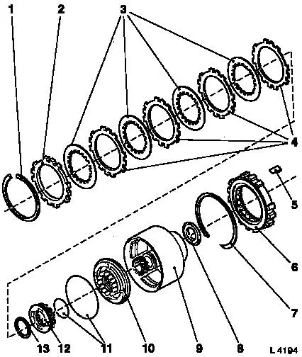
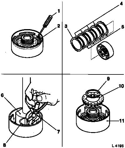
Multi-plate Clutch C3 and Freewheel F3,
Disassemble and Reassemble (AF 20)
Survey
|
1
|
Retaining ring
|
|
2
|
Flange
|
|
3
|
Lining plate C3
|
|
4
|
Steel plate C3
|
|
5
|
Overrunning clutch outer race bracket F3
|
|
6
|
Freewheel F3
|
|
7
|
Retaining ring
|
|
8
|
Thrust bearing
|
|
9
|
Clutch body
|
|
10
|
Piston C3
|
|
11
|
Seal rings
|
|
12
|
Return spring assembly
|
|
13
|
Retaining ring
|
|
|
 Remove Remove
Remove transmission – see operation "Transmission, Remove
and Install (AF 20)". Secure converter against falling out.
|
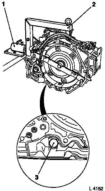
Attach transmission to KM-694-A (2). Attach assembly to KM-113-2
(1).
Remove fluid drain bolt (3), drain transmission fluid and
collect for damage diagnosis – see operation "Transmission
Fluid Condition, Check (AF 13-II/AF 17/AF 20/AF 22)".
Remove converter and fluid pump seal ring – see operation
"Converter and/or Fluid Pump Seal Ring, Replace (AF 13-II/AF 17/AF
20/AF 22)".
|
|
|
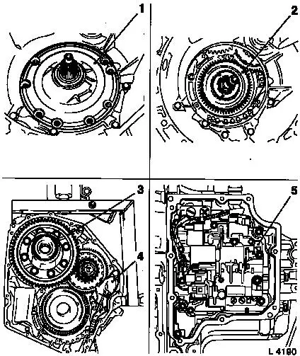
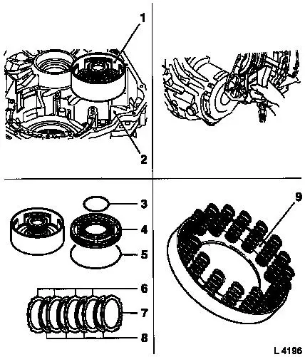
Remove fluid pump assembly (1) with multi-disc brake B1 and B2
– see operation "Fluid Pump Assembly with Multi-disc Brakes
B1 and B2, Remove and Install (AF 20)".
Remove freewheel F1 (2) – see operation "Freewheel F1,
Remove and Install (AF 20)".
Remove differential (3) – see operation "Differential,
Remove and Install (AF 20)".
Remove parking lock (4) – see operation "Parking Lock,
Remove and Install (AF 20)".
Remove valve body (5) – see operation "Valve Body, Remove
and Install (Transmission Removed) (AF 20)".
|
|
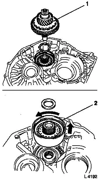
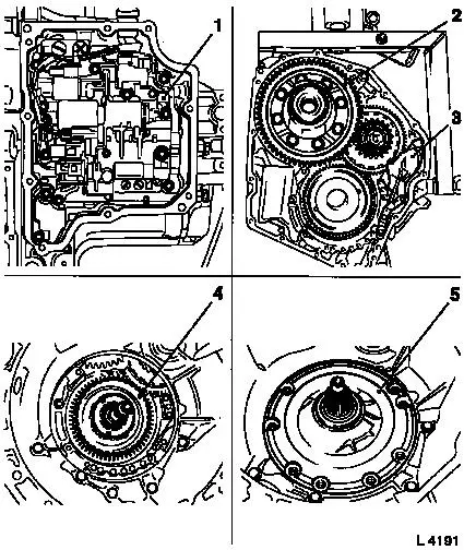
Remove planetary gear set P2 (1) – see operation
"Planetary Gear Set P2, Remove and Install (AF 20)".
|
Remove multi-plate clutch C3, freewheel F3 and brake band B4 (2)
– see operation "Multi-plate Clutch C3, Freewheel F3 and
Brake Band B4, Remove and Install (AF 20)".
|
|
 Disassemble
|
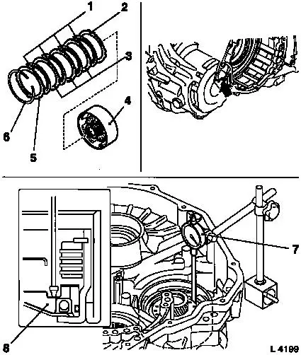
Prise out retaining ring (2) with screwdriver (1). Remove flange
(3), lining plates (4) and steel plates (5) from clutch body.
Compress return spring assembly (10) in press with KM-698 (6)
and KM-986. Release retaining ring (8) using KM-396 (7).
Remove retaining ring (9) with return spring assembly (10) from
clutch body (11).
|
|
Remove
|
Insert clutch body (1) into main housing (2). Blow in
low-pressure compressed air (4 bar); for this, cut off the end of
KM-994 in advance and insert KM-994 into bore hole. Assist with
pliers, if necessary. Replace O-rings (3 and 5) on piston (4).
 Inspect
Check flange (7), lining plates (8) and steel plates (6) for
damage and wear, replace if necessary. Lay new lining plates in
transmission fluid for at least 2 hours before installation.
Check return spring assembly (9). Replace if damaged.
|
|
|
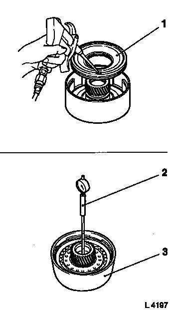
Check lock ball of piston C3 (1): Check if lock ball is free to
move by shaking. Check whether valve leaks using low pressure air
(4 bar).
 Measure
Measure inner diameter of front and rear clutch body bushing
– use Dial Gauge MKM-571-B (2) with probe for inner diameter,
carry out several measurements, take average. Measurement value:
28.5 to 28.525 mm.
If worn, replace clutch body (3); the bushings cannot be
replaced individually.
|
|
Inspect
|
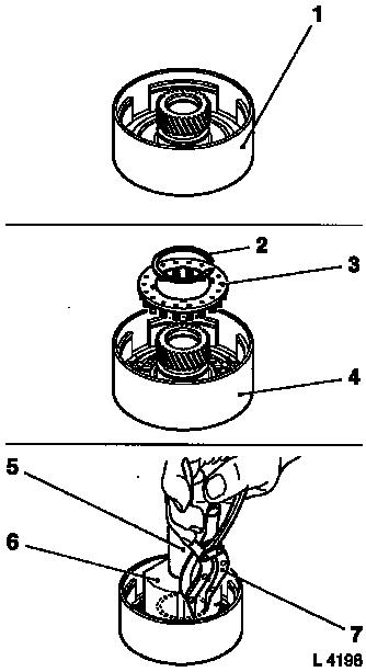
Check function surfaces of clutch body (1) for damage and wear,
replace if necessary.
 Assemble
Insert piston C3 (4) into clutch body – spring mount faces
upwards. Place return spring assembly (3) with retaining ring (2)
onto piston C3.
Compress return spring assembly on press with KM-698 (6) and
KM-986 (5). Attach retaining ring with KM-396 (7).
|
|
|
Insert flange (2) into clutch body (4). Alternately, insert
lining plate (3) first, then steel plate (1), flange (5) last into
clutch body – rounded side points to lining plate.
Fit retaining ring (6) into groove with screwdriver.
Measure
Measure piston stroke of multi-plate clutch C3: Insert clutch
body into transmission. Place dial gauge (7) onto piston C3 (8),
blow in low-pressure compressed air (4 bar, arrow); for this, cut
off the end of KM-994 in advance and insert KM-994 into bore hole.
If necessary, correct piston stroke by installing a suitable
compensation flange from the "Aftersales" division.
Measurement value: 1.52 to 1.89 mm.
|
|
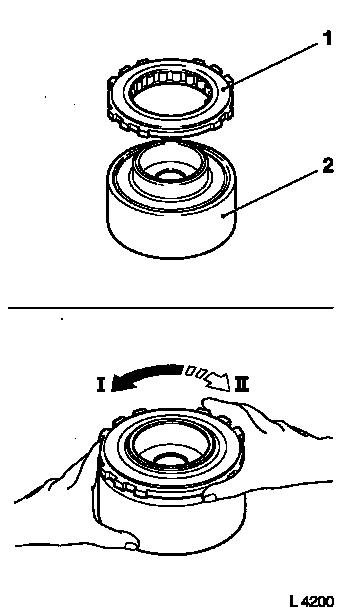
Inspect
Check functioning of overrunning clutch F3:
|
Fit freewheel (1) onto clutch body (2). Hold freewheel tightly,
clutch body must be able to turn anti-clockwise (I) and block
clockwise (II).
 Install
Install multi-plate clutch C3, freewheel F3 and brake band B4
– see operation "Multi-plate Clutch C3, Freewheel F3 and
Brake Band B4, Remove and Install (AF 20)".
|
|
Install planetary gear set P2 – see operation "Planetary
Gear Set P2, Remove and Install (AF 20)".
Install valve body (1) – see operation "Valve Body, Remove
and Install (Transmission Removed) (AF 20)".
|
Install parking lock (3) – see operation "Parking Lock,
Remove and Install (AF 20)".
Install differential (2) – see operation "Differential,
Remove and Install (AF 20)".
Install freewheel F1 (4) – see operation "Freewheel F1,
Remove and Install (AF 20)".
Install fluid pump assembly (5) with multi-disc brake B1 and B2
– see operation "Fluid Pump Assembly with Multi-disc Brakes
B1 and B2, Remove and Install (AF 20)".
|
|
Install
Install fluid pump seal ring and converter – see operation
"Converter and/or Fluid Pump Seal Ring, Replace (AF 13-II/AF 17/AF
20/AF 22)". Secure converter against falling out.
|
Attach fluid drain bolt (3) with new seal ring to transmission
– tightening torque 40 Nm / 29.5 lbf. ft.
Remove transmission assembly from KM-113-2 (1) with
KM-694-A.
Remove transmission from KM-694-A (2).
Install transmission – see operation "Transmission, Remove
and Install (AF 20)".
Charge transmission fluid.
Inspect
Check and correct level of transmission fluid – see
operation "Transmission Fluid Level, Check and Correct (AF 13-II/AF
17/AF 20/AF 22)".
|
|
|
