|
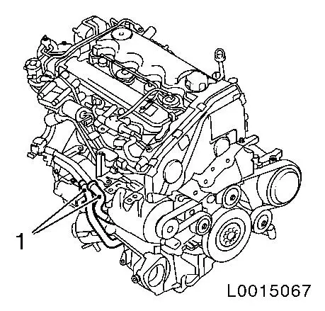
Replace intake manifold
 Remove Remove
| 2. |
Disconnect battery
| • |
Detach ground connection from ground terminal
|
|
| 3. |
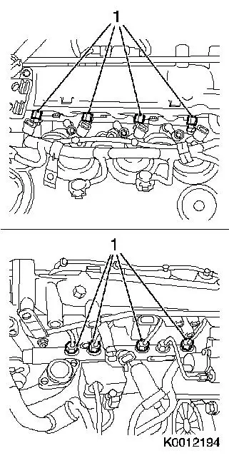
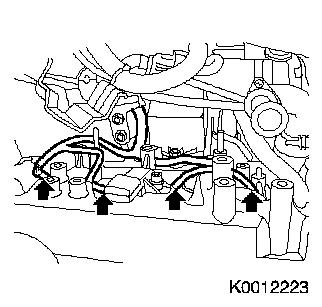
Detach wiring harness
| • |
Disconnect 4x wiring harness plugs for injector (2)
|
|
|
|
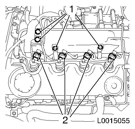
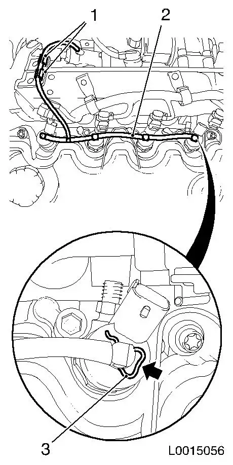
| 4. |
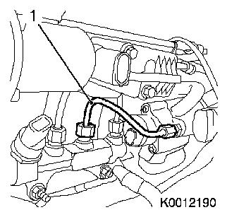
Detach 4x oil leak line (2) from injectors
Note: The oil leak line
must not be detached from the fuel return damping case. It if is
detached, it must be replaced.
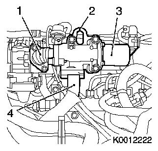
| • |
Release 4x retaining clamp (3) from injector in direction of
arrow
| – |
Pull off oil leak line
Note: Close 4x
injectors with suitable
Sealing plug
1)
|
|
| • |
Unclip 2x oil leak line from bracket (1)
|
|
|
|
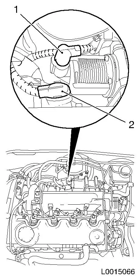
| 5. |
Disconnect 2x wiring harness plugs
| • |
From exhaust gas recirculation (1)
|
| • |
From boost pressure sensor (2)
|
|
|
|
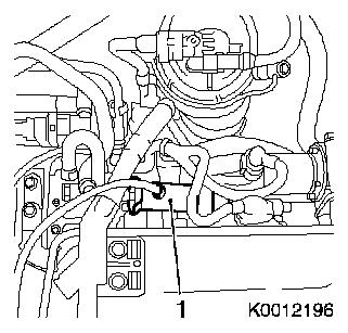
| 6. |
Remove fuel return damping case (1) with oil leak line
Note: Open fuel
connections must be sealed with appropriate plugs
1)
| • |
Return line with KM-796-A
|
|
|
|
| 7. |
Detach accumulator high pressure line (1) to high pressure
pump
Important: When releasing the
retaining nut on the high pressure pump, counterhold with
open-ended wrench.
|
| • |
Unscrew 2x union nuts
Note: Opened fuel
connections must be
sealed off with suitable sealing plugs
1)
|
|
|
|
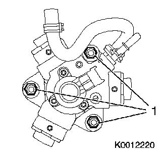
| 8. |
Detach 4x high pressure line - accumulator to injector
Important: When releasing the
retaining nut, counterhold with open-ended wrench against the
injector
|
| • |
Unscrew 8x union nut (1)
Note: Close opened fuel
connections with appropriate plugs
1)
|
|
|
|
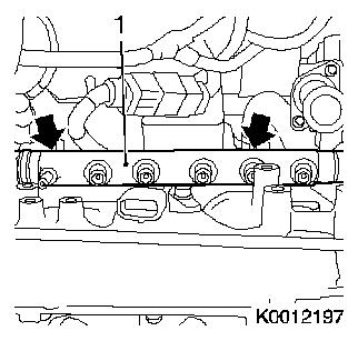
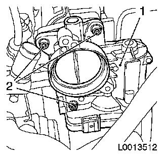
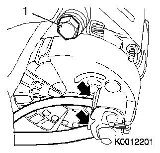
| 9. |
Remove accumulator (1)
| • |
Unscrew 2x nut (arrows)
|
| • |
Disconnect 2x wiring harness plugs
|
|
|
|
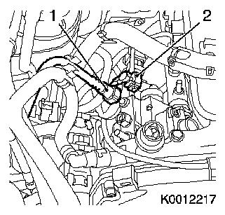
| 10. |
Detach fuel line of high-pressure pump (1)
| • |
Release clamp
Note: Close opened fuel
connections with appropriate plugs
1)
|
|
| 11. |
Disconnect high-pressure pump wiring harness plug (2)
|
|
|
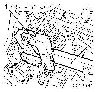
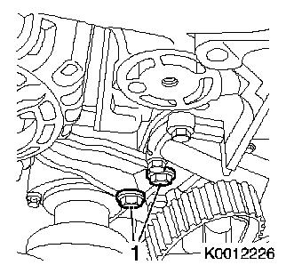
| 12. |
Release high-pressure pump drive gear
| • |
Counterhold with KM-6347 (1) in
combination with KM-956-1 (2)
|
|
|
|
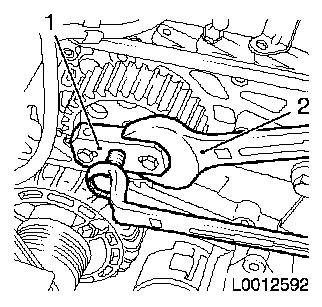
| 13. |
Remove high-pressure pump gear
| • |
Pull off high-pressure pump drive gear
| – |
Counterhold with open-ended wrench (2)
|
|
|
|
|
| 14. |
Remove high pressure pump
|
|
|
| 15. |
Raise vehicle by its full height
|
| 16. |
Place collecting basin underneath.
|
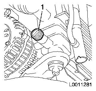
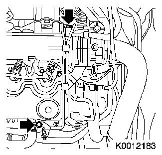
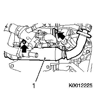
| 17. |
Drain coolant
| • |
Open drain bolt on radiator (1)
|
|
|
|
| 18. |
Detach 2x coolant hoses (1) from coolant pipe
|
|
|
| 19. |
Lower vehicle by its full height
|
| 20. |
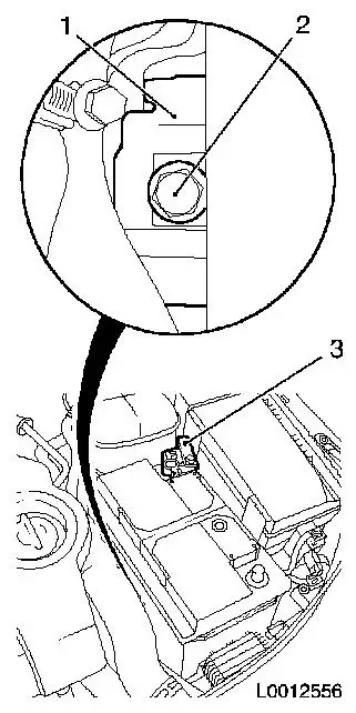
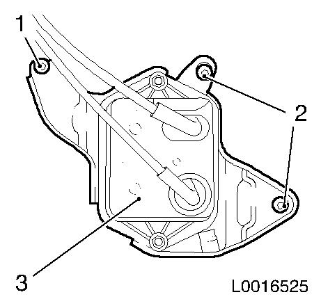
Remove battery
| • |
Detach positive terminal (3) from positive pole
|
| • |
Remove battery insulation
|
|
|
|
| 21. |
Remove battery support.
| • |
Remove pre-glow system control unit (4)
|
| • |
Unclip coolant hose bracket (5)
|
|
|
|
| 22. |
Detach vacuum line
| • |
Detach 4x vacuum hose from vacuum line
Note: Mark the
assignment of the hoses
|
| • |
Unscrew 2x bolts (arrows)
|
|
|
|
| 23. |
Detach EGR valve
| • |
EGR metal tube to throttle valve module (1)
|
| • |
Exhaust gas recirculation (EGR) cooler (4)
|
| • |
Remove 2x engine transport shackle seal (2)
|
|
|
|
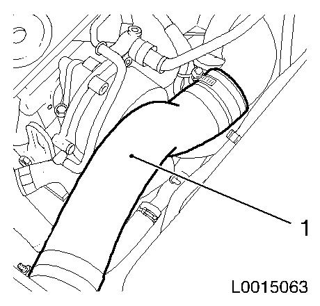
| 24. |
Detach intercooler charge air hose (1) from throttle body
|
|
|
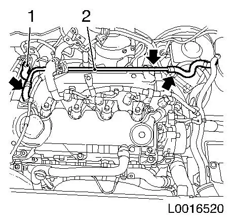
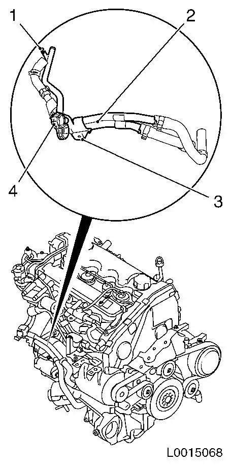
| 25. |
Detach vacuum line from vacuum pump
| • |
Disconnect quick-release fitting (2)
|
| • |
Unclip 2x vacuum line from bracket (1)
|
|
|

|
| 26. |
Remove throttle valve module (1)
| • |
Disconnect wiring harness connector.
|
|
|
|
| 27. |
Unclip coolant return line (2)
| • |
Remove 3x hoses (arrows)
|
|
|
|
| 28. |
Remove 4x wiring harness plugs from glow plugs (arrows)
|
|
|
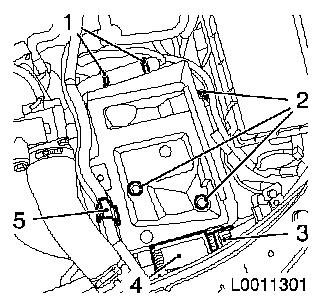
| 29. |
If present: remove vacuum reservoir (3) with retaining
plate
| • |
Unscrew 3x bolts (1) and (2)
|
|
|
|
| 30. |
Remove coolant pipe (2)
| • |
Unclip 2x coolant hoses from bracket (4)
|
| • |
Detach from bracket on transmission (3)
|
| • |
Detach from bracket on thermostat housing (1)
|
| • |
Detach 2x coolant hoses
|
|
|
|
| 31. |
Remove EGR cooler (1)
Note: Remove EGR cooler
rearward
| • |
Unscrew bolt, nut (arrows)
|
| • |
Detach 2x coolant hoses
|
|
|
|
| 32. |
Release alternator bracket
| • |
Unscrew 2x bolts (1)
Note: Note different
bolts
|
|
|
|
| 33. |
Detach alternator
Note: Set alternator
aside
|
|
|
Important: Note guide sleeves
|
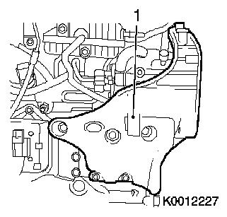
| 34. |
Detach high-pressure pump bracket (1)
| • |
Unscrew 6x bolts
Note: Note different
bolt lengths
|
|
|
|
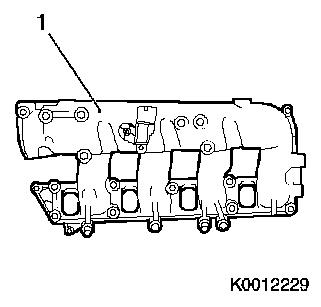
| 35. |
Remove intake manifold (1)
|
|
|
| 36. |
Detach charge pressure sensor
|
| 37. |
Unscrew coolant hose connection port
|
 Install
| 38. |
Tighten coolant hose connection port
Note: coat with
sealant
|
| 39. |
Attach charge pressure sensor
|
| 40. |
Clean sealing surface
|
| 41. |
Install intake manifold
| • |
Install new gasket
| – |
Clip on 2x to intake manifold
|
|
| • |
Tighten 9x new nut 25 Nm
|
|
Important: Note guide sleeves
|
| 42. |
Attach high-pressure pump bracket
|
| 44. |
Fasten alternator bracket
| • |
Tighten 2x bolt 25 Nm
Note: Note different
bolts
|
|
| 46. |
Install EGR cooler
| • |
Attach 2x coolant hoses
|
|
| 47. |
Install coolant pipe
| • |
Attach 2x coolant hoses
|
| • |
Clip 2x coolant hoses into bracket
|
|
| 48. |
If present: install vacuum reservoir with retaining plate
|
| 49. |
Connect 4x wiring harness plug, sheathed glow plug
|
| 50. |
Install coolant return line
|
| 51. |
Install throttle valve module
| • |
Tighten 3x bolts
Note: Attach wiring
harness bracket to throttle valve module
|
| • |
Fix wiring harness plug
|
|
| 52. |
Attach vacuum line to vacuum pump
Important: Quick-release fitting
must audibly engage
|
| • |
Connect quick release fitting
|
| • |
Clip 2x vacumhoses into bracket
|
|
| 53. |
Fit intercooler charge air hose to throttle valve
connection
Note: Charge air hose
and connection piece must be free from oil and grease
| • |
Tighten 2x clamp 3.5 Nm
|
|
| 54. |
Install EGR valve
| • |
Fit engine transport shackle
|
| • |
EGR metal tube to throttle valve module
|
| • |
Exhaust gas recirculation (EGR) cooler
|
|
| 55. |
Install vacuum line
| • |
Attach 4x vacuum hose to vacuum line
Note: Note the
assignment of the hoses
|
|
| 56. |
Raise vehicle by its full height
|
| 57. |
Attach 2x coolant hoses to coolant pipe
|
| 58. |
Lower vehicle by its full height
|
| 59. |
Install battery holder
| • |
Attach pre-glow system control device
|
| • |
Clip on coolant hose bracket
|
|
| 60. |
Install battery
| • |
Insert battery insulation
|
| • |
Attach positive connection to positive terminal
|
|
| 61. |
Install high pressure pump
|
| 62. |
Fit high pressure pump wheel
| • |
Counterhold with KM-6347 in
conjunction with KM-956-1
|
|
| 63. |
Connect high-pressure pump wiring harness plugs
|
| 64. |
Attach fuel line to high-pressure pump
|
| 65. |
Install accumulator
| • |
Connect 2x wiring harness plugs
|
|
Important: High-pressure lines
must not be installed more than once. When fastening the retaining
nut counterhold against the injector with an open-ended wrench.
|
| 66. |
Install 4x new high-pressure line, accumulator to injector
| • |
Tighten 4x retaining nut (M14) 23
Nm
|
| • |
Tighten 4x retaining nut (M12) 23
Nm
|
|
Important: High-pressure lines
must not be installed more than once. When fastening the retaining
nut counterhold against the injector with an open-ended wrench.
|
| 67. |
Attach new high pressure line - accumulator to high pressure
pump
| • |
Tighten union nut (M14) 23 Nm
|
| • |
Tighten union nut (M12) 23 Nm
|
|
| 68. |
Install fuel return damping case with oil leak line
| • |
Tighten 2x bolts
| – |
Attach wiring harness bracket to fuel return damping case
|
|
|
| 69. |
Connect 2x wiring harness plugs
| • |
To exhaust gas recirculation
|
| • |
To boost pressure sensor
|
|
| 70. |
Attach wiring harness
| • |
Connect 4x injector wiring harness plug
|
|
| 71. |
Attach 4x oil leak line to injector
| • |
Clip 4x oil leak line to injector
|
| • |
Clip 2x oil leak line in bracket
|
|
| 72. |
Connect battery
| • |
Attach ground connection to ground terminal
|
|
| 73. |
Fuel System, Check for Leaks
Important: Wear protective
goggles and protective gloves.
|
| • |
Start engine.
Note: Check fuel system
for escaping fuel.
|
|
| 74. |
Top up coolant or ensure correct quantity is present. 
|
1 ) protective caps are available in the opel parts
catalogue under catalogue number 45 06 154 / part number 9201697/
|
