|
Engine, Remove and Install
 Remove Remove
Important: Move steering wheel to
straight-ahead position
|
| 2. |
Remove steering column interim spindle
| • |
Engage steering wheel lock
|
|
|
|
| 3. |
Disconnect battery
| • |
Detach ground connection from ground terminal
|
|
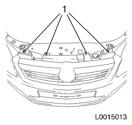
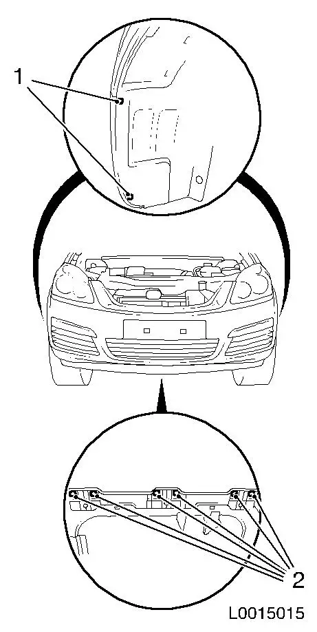
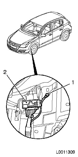
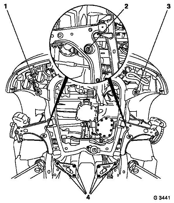
| 5. |
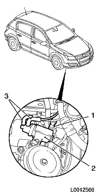
Detach radiator grille (2)
| • |
Detach 4x body-bound rivets (1)
|
| • |
Release 6x lugs from front panelling
|
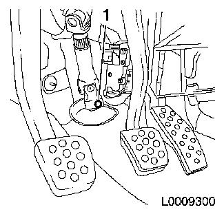
|
|
|
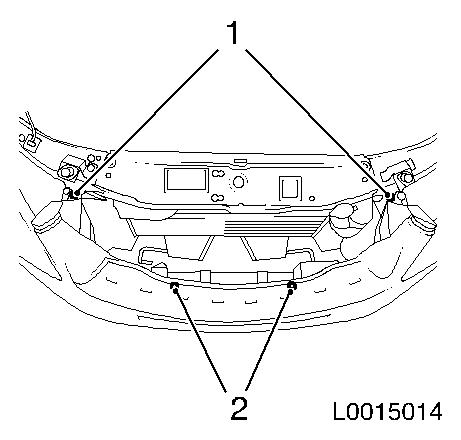
| 6. |
Detach front panelling at top
| • |
Remove 2x body-bound rivets (2)
|
| • |
Disconnect wiring harness connector.
|
|
|
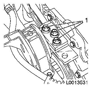
|
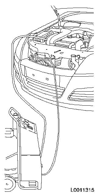
| 7. |
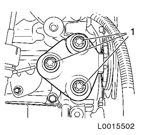
Empty climate control system
| • |
Connect service station
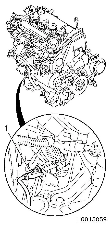
|
| • |
Blue hose to low-pressure service connection with small
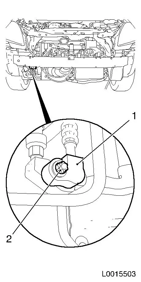
diameter
|
| • |
Red hose to high-pressure service connection with large
diameter
Note: Read Service
Station operating instructions carefully
|
| • |
Determine quantity of condenser extracted at the oil separator
of the Service Station
|
|
|
|
| 8. |
Undo 2x front wheels
| • |
Slacken 10x wheel bolts
|
|
| 9. |
Raise vehicle by half its height
|
| 10. |
Remove 2x front wheels
| • |
Unscrew 10x wheel bolts
|
|
| 11. |
Remove front panelling
| • |
Remove 6x body-bound rivets (2)
|
|
|
|
| 12. |
Remove front panelling
Note: Use a second
person
| • |
Push front panelling upwards at side and pull out of
bracket
|
| • |
Detach front panelling from bracket
|
| • |
Unclip outside temperature sensor
|
|
| 13. |
Raise vehicle by half its height
|
| 14. |
Detach the lower engine cover and right engine splash guard
|
| 15. |
Place collecting basin underneath.
|
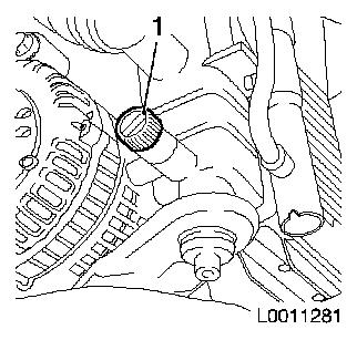
| 16. |
Drain coolant
| • |
Open drain bolt on radiator (1)
|
|
|
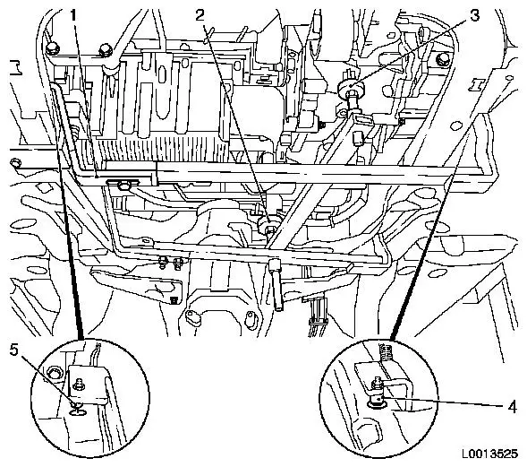
|
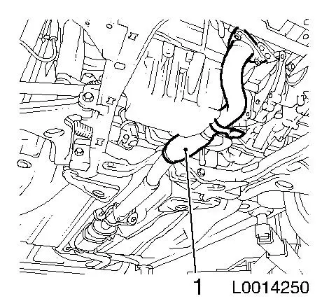
Important: Protect the exhaust
pipe from uncontrolled sagging as deflection as little as 5-10
degrees from the prescribed installation position could damage the
flex pipe housed within it.
|
| 17. |
Remove front exhaust pipe (1)
| • |
Detach from particle filter flange
|
| • |
Detach from pre-catalytic converter
|
|
|
|
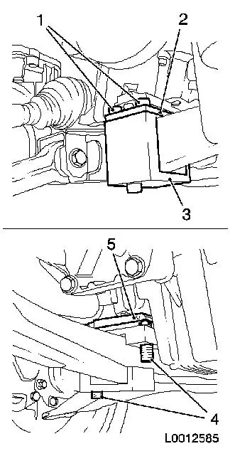
| 18. |
Fit and adjust KM-6397
| • |
Fit KM-6397
| – |
Insert upper bracket (2) with support plate below lower oil
pan
|
| – |
Attach lower bracket (3)
|
|
| • |
Adjust KM-6397
| – |
Screw in 2x adjusting bolts (4)
Note: Support plate (5)
must lie flat against oil pan
|
|
|
|
|
|
| 19. |
Fit KM-6001-A
Note: Attaching KM-6001-A guarantees perfect alignment of the
drive unit with the front axle body
| • |
Detach front right bracket (1)
|
| • |
Attach front right bracket
|
| • |
Insert journals (4) and (5) in guide holes in front axle
body
|
| • |
Tighten 2x guide rails
| – |
Tighten 3x bolted connections
|
|
| • |
Adjust support bearings (2) and (3)
Note: The guide
journals must be seated free from play in the support bearings
|
|
|
| 20. |
Lower vehicle by its full height
|
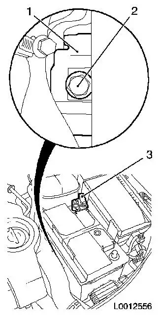
| 21. |
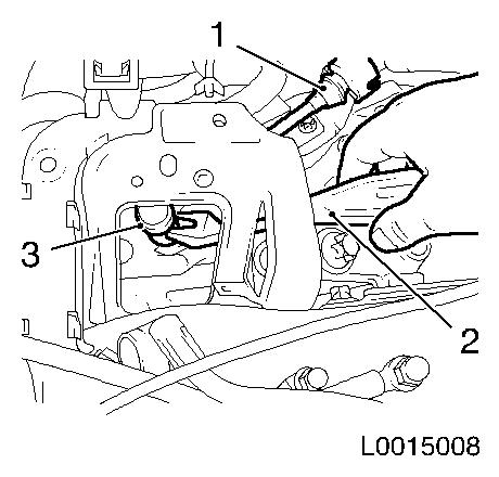
Remove battery
| • |
Detach positive terminal (3) from positive pole
|
| • |
Remove battery insulation
|
|
|
|
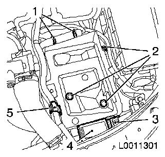
| 22. |
Remove battery support.
| • |
Remove pre-glow system control unit (4)
|
| • |
Unclip coolant hose bracket (5)
|
|
|
|
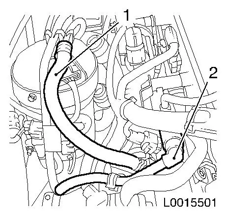
| 23. |
Detach 3x coolant hose (1) from coolant expansion tank
|
|
|
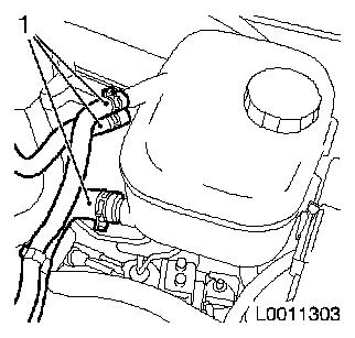
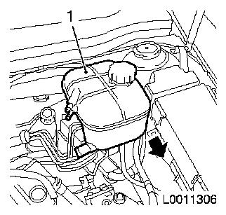
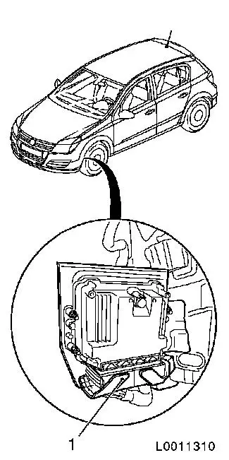
| 24. |
Remove coolant expansion tank (1)
| • |
Pull from bracket in direction of arrow
|
|
|
|
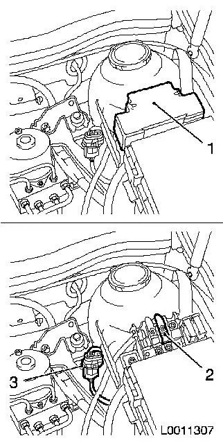
| 25. |
Disconnect steering wiring harness
| • |
Remove fuse carrier cover (1)
|
| • |
Detach positive cable (2) from fuse carrier
Note: Mark installation
position
|
| • |
Disconnect wiring harness connector (3)
|
| • |
Detach earth cable from negative battery terminal
|
| • |
Expose wiring harness and put aside on drive unit
|
|
|
|
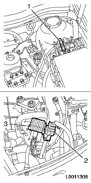
| 26. |
Disconnect upper engine timing wiring harness
| • |
Detach positive cable (1) from fuse carrier
Note: Mark installation
position
|
| • |
Release and unplug wiring harness plug (2)
|
| • |
Put engine timing wiring harness with pre-heating system
control unit (3) aside on drive unit
|
|
|
|
| 27. |
Disconnect starter wiring harness (1)
| • |
Disconnect wiring harness connector (3)
|
| • |
Detach wiring harness from positive terminal
|
| • |
Detach earth connection wiring harness from body
|
| • |
Put wiring harness aside onto drive unit
|
|
|
|
| 28. |
Detach selector lever actuation cable
| • |
Lever out head (3) from selector lever with KM-569-A (2)
|
| • |
Unclip cable (1) upward
|
|
|
|
| 29. |
Disconnect 2x coolant hose (1) from heater core
| • |
Release 2x coolant hoses in direction of arrow
Note: Mark
affiliation
|
|
|
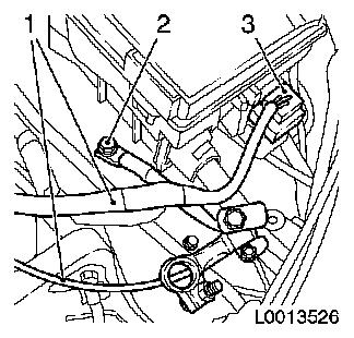
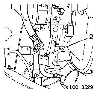
|
| 30. |
Remove brake servo vacuum line
| • |
Disconnect quick-release fitting (2)
|
|
|

|
| 31. |
Detach 2x fuel line from fuel return damping case
Note: Open fuel
connections must be sealed with appropriate plugs
| • |
Detach fuel return line (2) with KM-796-A
| – |
Unclip fuel line from bracket
|
|
| • |
Detach fuel supply line (1) from high-pressure pump
|
|
|
|
| 32. |
Remove air cleaner housing
|
| 33. |
Disconnect air conditioning low pressure line (1)
| • |
Unclip wiring harness of turbocharger solenoid valve from low
pressure line
|
|
|
|
| 34. |
Detach right engine damping block from engine damping block
adapter
|
|
|
| 35. |
Detach left engine damping block from transmission
|
|
|
| 36. |
Raise vehicle by half its height
|
| 37. |
Detach AC high pressure line (1) from pressure sensor
|
|
|
| 38. |
Disconnect turbocharger solenoid valve (2)
| • |
Disconnect 2x vacuum lines (3)
Note: Mark vacuum
line
|
| • |
Disconnect wiring harness plug (1)
|
|
|
|
| 39. |
Detach cooling module wiring harness
| • |
Disconnect wiring harness plug (2)
|
|
|
|
| 40. |
Detach wiring harness from engine control unit
| • |
Release and unplug wiring harness plug (1) from engine control
unit
|
| • |
Unclip wiring harness from bracket
|
| • |
Unclip 2x wiring harness from body
|
|
|
|
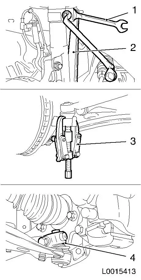
| 41. |
Detach 2x swing arms (2)
| • |
Unscrew 2x nuts
| – |
Use spanner (1) to hold against flat surface
|
|
|
| 42. |
Detach 2x tie rods
| • |
2x nuts
| – |
Use KM-161-B (3) to press out of
steering knuckle
|
|
|
| 43. |
Detach 2x steering knuckle pins
| • |
Detach 2x screw connections
|
| • |
Spread steering knuckle pins with KM-915 (4) and draw guiding joint out of steering
knuckle
|
|
|
|
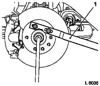
| 44. |
Detach 2x axle shafts
| • |
Unscrew 2x nuts
| – |
Counterhold at wheel hub with KM-468-B (1)
|
|
|
|
|
| 45. |
Raise vehicle by half its height
|
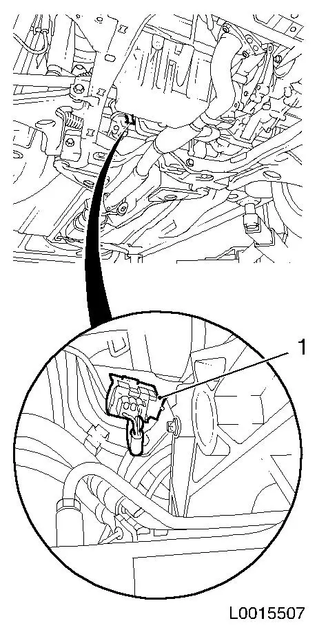
| 46. |
Unplug wiring harness plug of particle filter temperature
sensor (1)
| • |
Unclip wiring harness plug from bracket
|
| • |
Unclip wiring harness from front axle body bracket
|
|
|
|
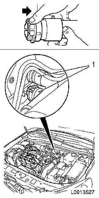
| 47. |
Release and unplug bulkhead wiring harness plug (1)
|
|
|
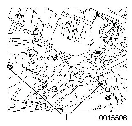
| 48. |
Remove 2x underbody closure plug (1)
|
|
|
|
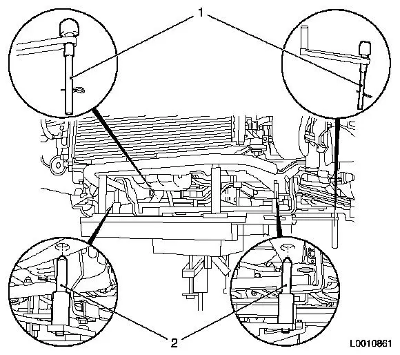
| 49. |
Fit KM-904 in conjunction with KM-6390
| • |
Attach to hydraulic lifter
Note: Use hydraulic
jack that can be lowered to a height of at least 100 cm
|
| • |
Lower centring pins (1)
|
| • |
Place under front axle body, ensure there is no play
| – |
Centring pins (2) must engage in the relevant holes in the
front axle body
|
|
|
|
|
Important: Do not use an impact
screwdriver!
|
| 50. |
Remove front axle body
| • |
Unscrew 10x bolts (1...4)
Note: Note different
bolt lengths
|
|
|
Important: Ensure that no
attached parts are damaged.
|
| 51. |
Move out front axle body with engine
Note: Use a second
person
|
| 52. |
Check thread
| • |
Check ease of movement of 10x cage nuts, replacing if
necessary
|
|
Important: Ensure that no
attached parts are damaged.
|
| 53. |
Raise and align front axle body
Note: Use a second
person
| • |
Insert centring pins in underbody
|
|
 Install
Important: Do not use an impact
screwdriver!
|
| 54. |
Fit front axle body
| • |
Tighten 10x new bolt 90 Nm + 45° +
15°
Note: Note different
bolt lengths
|
|
| 55. |
Detach KM-904 together with KM-6390
|
| 56. |
Install 2x underbody closure plug
|
| 57. |
Lower vehicle by its full height
|
| 58. |
Attach right engine damping block to engine damping block
adapter
|
| 59. |
Attach left engine damping block to transmission
|
| 60. |
Connect air conditioning low pressure line
| • |
Clip wiring harness of turbocharger solenoid valve to low
pressure line
|
|
| 61. |
Install air cleaner housing 
|
| 62. |
Attach 2x fuel line to fuel return damping case
| • |
Attach fuel return line to high-pressure pump
|
| • |
Attach fuel supply line
|
|
Warning: Connection must audibly
engage
|
| 63. |
Connect brake servo vacuum line
|
| 64. |
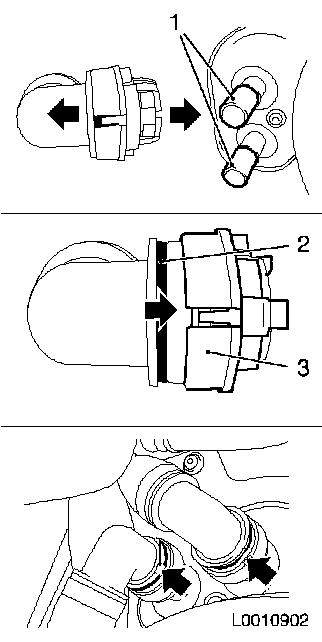
Attach 2x coolant hoses to heater core
| • |
Slide 2x quick release fitting locking mechanisms in direction
of arrow as far as they will go
| – |
The plastic rings (blue) are hidden
|
|
| • |
Fit 2x quick release fittings onto heater core connecting piece
(1) as far as they will go
Note: Pay attention to
coloured markings!
|
| • |
Slide 2x quick release fitting locking mechanisms (3) in
direction of arrow as far as they will go
| – |
The plastic rings (blue) must be visible
|
|
| • |
Check that quick release fittings are correctly seated and that
plastic rings (arrows) are visible
|
|
|
|
Important: Shift cables must not
be stretched, twisted or kinked.
|
| 65. |
Attach selector lever actuation cable
| • |
Clip in cable from above
|
| • |
Clip head into selector lever
|
|
| 66. |
Connect starter wiring harness
| • |
Connect and lock wiring harness plug
|
| • |
Attach earth connection wiring harness to body
|
| • |
Attach wiring harness to positive terminal
|
|
| 67. |
Connect engine timing wiring harness (top)
| • |
Attach positive cable to fuse carrier
Note: Pay attention to
installation position.
|
| • |
Connect and lock wiring harness plug
|
|
| 68. |
Connect steering wiring harness
| • |
Fix wiring harness plug
|
| • |
Attach positive cable to fuse carrier
Note: Pay attention to
installation position
|
| • |
Attach earth cable to negative battery terminal
|
| • |
Install fuse carrier cover
|
|
| 69. |
Install coolant expansion tank
|
| 70. |
Attach 3x coolant hose to coolant expansion tank
|
| 71. |
Raise vehicle by half its height
|
| 72. |
Install 2x axle shafts into wheel hub
| • |
Insert guiding joint into steering knuckle
|
| • |
Tighten 2x nut 150 Nm , slacken
45° , then tighten to 250 Nm
|
| • |
Counterhold at wheel hub with KM-468-B
|
|
| 73. |
Attach 2x guide joints to steering knuckle
| • |
Tighten 2x new screwed joint 50
Nm
|
|
| 74. |
Attach 2x tie rods to steering knuckle
| • |
Tighten 2x new nut 30 Nm + 90° +
15°
|
|
| 75. |
Attach 2x swing arms to spring strut support tube
Note: Use spanner to
counterhold against flat surface
| • |
Tighten 2x new nut 55 Nm
|
|
| 76. |
Attach wiring harness to engine control unit
| • |
Connect wiring harness plug to control unit
|
| • |
Clip wiring harness into bracket
|
| • |
Clip in 2x wiring harness to body
|
|
| 77. |
Attach cooling module wiring harness
| • |
Connect and lock wiring harness plug
|
| • |
Clip in 3x wiring harness brackets
|
|
| 78. |
Connect charge air control solenoid valve
| • |
Connect 2x vacuum lines
Note: Pay attention to
marks.
|
| • |
Fix wiring harness plug
|
|
| 79. |
Attach AC high pressure line to pressure sensor
|
| 80. |
Raise vehicle by half its height
|
| 83. |
Connect wiring harness plug of particle filter temperature
sensor
| • |
Clip wiring harness plug into bracket
|
| • |
Clip wiring harness into front axle body bracket
|
|
| 84. |
Connect and lock bulkhead wiring harness plug
|
| 85. |
Install front exhaust pipe
Important: Prevent exhaust system
from sagging in an uncontrolled manner. Even flex pipe bending of 5
- 10 degrees from intended installation position can cause damage
that may result in total failure of the flex pipe
|
| • |
Replace 2x seals
|
| • |
Attach to particle filter flange
| – |
Tighten 3x new nut 20 Nm
|
|
| • |
Attach to pre-catalytic converter
| – |
Tighten 3x new nut 20 Nm
|
|
| • |
Attach to oil pan
| – |
Apply assembly paste (white)
|
|
|
| 86. |
Install lower engine cover and right engine splash guard
|
| 87. |
Lower vehicle by half its height
|
| 88. |
Install front panelling
Note: Use a second
person
| • |
Clip in outside temperature sensor
|
| • |
Attach front panelling to bracket
|
| • |
Clip in the front panelling on the side
|
|
| 89. |
Attach front panelling at bottom
| • |
Install 6x body-bound rivets
|
|
| 90. |
Fit 2x front wheels
| • |
Screw in 10x wheel bolts
|
|
| 91. |
Lower vehicle by half its height
|
| 92. |
Fasten 2x front wheels
| • |
Tighten 10x wheel bolt 110 Nm
|
|
| 93. |
Attach front panelling at top
| • |
Fasten 2x body-bound rivets
|
|
| 94. |
Install battery holder
| • |
Attach pre-glow system control device
|
| • |
Clip on coolant hose bracket
|
|
| 95. |
Install battery
| • |
Insert battery insulation
|
| • |
Attach positive connection to positive terminal
|
|
| 96. |
Evacuate and charge air conditioning system
| • |
Connect service station
|
| • |
Connect blue hose to low pressure service connection with small
diameter
|
| • |
Connect red hose to high pressure service connection with large
diameter
Note: Read Service
Station operating instructions carefully.
|
| • |
Use the Service Station to insert the quantity of new
compressor lubricant into the climate control system that was
extracted when it was emptied.
| – |
Fill air conditioning system with R 134a refrigerant
|
|
|
|
|
| 97. |
Connect battery
| • |
Attach ground connection to ground terminal
|
|
| 99. |
Install radiator grille
| • |
6x clip in front panelling
|
| • |
Install 4x body-bound rivets
|
|
| 100. |
Install steering column intermediate shaft clamp bolt
| • |
Tighten new bolt 22 Nm
Note: Clean thread
before re-using and insert bolt with locking compound (blue). The
maximum installation time including torque check is 10 minutes.
|
|
| 101. |
Top up coolant or ensure correct quantity is present.
|
| 102. |
Program volatile memories
|
|
