|
Crankshaft, Remove and Install - Diesel engine
 Remove Remove
| 2. |
Place collecting basin underneath.
|
| 4. |
Remove right engine damping block bracket
|
| 5. |
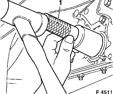
Remove injector wiring harness retaining plate (1)
| • |
Set retaining plate aside
|
|
|
|
| 6. |
Detach camshaft sensor (1)
| • |
Disconnect wiring harness connector.
|
|
|
|
| 7. |
Detach toothed belt cover (top)
| • |
Unscrew 8x bolts
Note: Note different
bolt lengths
|
| • |
Unclip 4x fuel return line
|
|
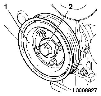
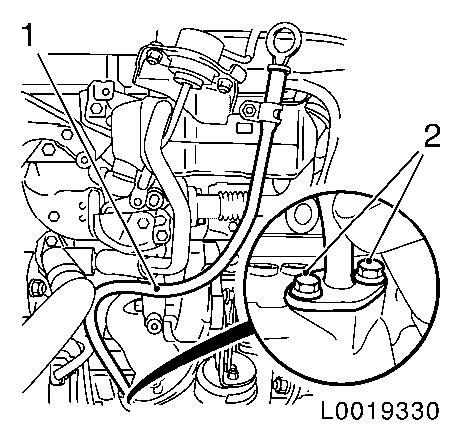
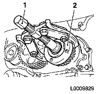
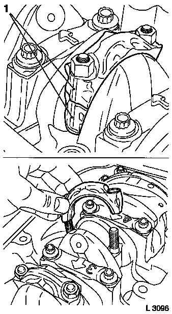
| 8. |
Remove torsional vibration damper (1)
| • |
Unscrew 4x bolts
Note: Counterhold at
bolt (2)
|
|
|
|
| 9. |
Remove lower toothed belt cover (1)
| • |
Remove engine damping block adapter
|
|
|
|
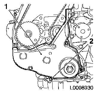
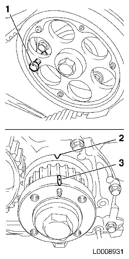
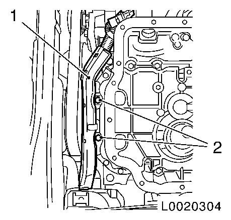
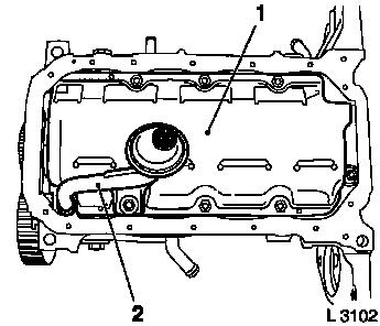
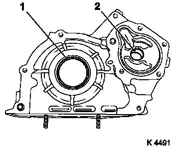
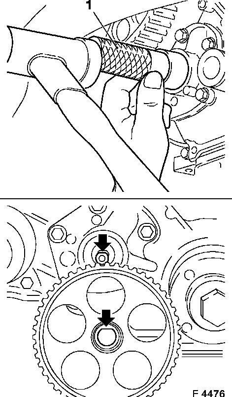
| 10. |
Set cylinder 1 to TDC of combustion stroke
| • |
Fix camshaft sprocket in position using TDC locking bolt
(M6x25) (1)
|
| • |
Turn crankshaft evenly in direction of engine rotation, until
mark (3) of toothed belt drive gear is in line with mark (2) on oil
pump cover
|
|
|
|
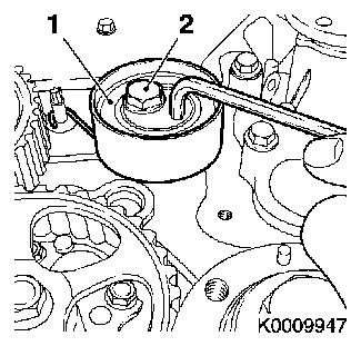
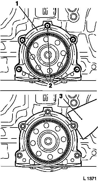
| 11. |
Release toothed belt tension roller (1)
| • |
Slacken bolt of toothed belt tension roller (2)
|
| • |
Turn toothed belt tension roller approx. 90°
anticlockwise
|
| • |
Tighten bolt - toothed belt tension roller
|
|
|
|
| 12. |
Remove toothed belt
| • |
Mark direction of rotation
|
|
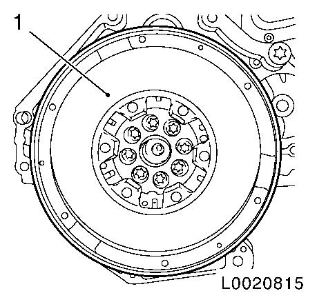
| 13. |
Lock flywheel with KM-652
|
| 14. |
Remove thrust plate and clutch disk 
|
| 16. |
Remove locking tool KM-652
|
| 17. |
Using KM-412-A , turn engine through
180°
|
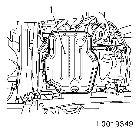
| 18. |
Remove lower part of oil pan
| • |
Detach lower part of oil pan with KM-J-37228
|
|
|
|
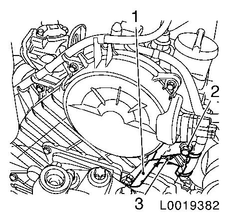
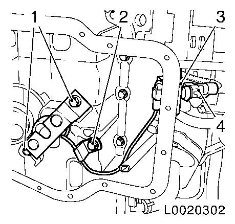
| 19. |
Remove residual oil quantity sensor
| • |
Disconnect wiring harness plug (4)
|
| • |
Release retaining clamp (3)
|
| • |
Unscrew 2x bolt (1 and 2)
|
|
|
|
| 20. |
Detach oil dipstick guide tube (1)
| • |
From cooler, exhaust gas recirculation
|
|
|
|
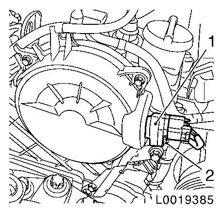
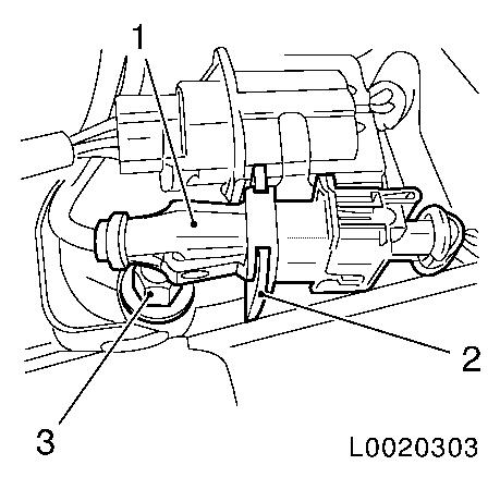
| 21. |
Detach bracket for wiring harness plug (2)
| • |
Unclip wiring harness plug (1)
|
|
|
|
| 22. |
Release wiring trough (1)
|
|
|
| 23. |
Remove upper part of oil pan
|
| 24. |
Detach oil intake pipe (2)
|
| 25. |
Detach oil baffle plate (1)
|
|
|
| 26. |
Detach toothed belt drive gear (1)
| • |
Unscrew bolt
| – |
Counterhold with KM-662-C
|
|
| • |
Remove with KM-161-B (1)
|
|
|
|
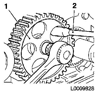
| 27. |
Detach oil pump gear (1)
| • |
Unscrew nut
Note: Counterhold with
socket wrench (2)
|
|
|
|
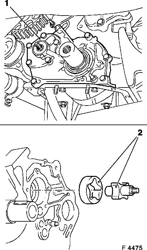
| 28. |
Remove oil pump cover (1)
| • |
Unscrew 9x bolts
Note: Note different
bolt lengths
|
| • |
Remove inner rotor and outer rotor (2)
|
|
|
|
| 29. |
Remove crankshaft seal ring (1)
Important: Do not damage sealing
surfaces
|
| • |
Prise out seal ring
|
|
| 30. |
Install oil pump seal ring (2)
Important: Do not damage sealing
surfaces
|
| • |
Prise out seal ring
|
|
|
|
| 31. |
Detach bracket for crankshaft seal ring (1) from cylinder
block
| • |
Separate crankshaft rear seal ring bracket (1) from cylinder
block using a suitable tool (3)
|
|
|
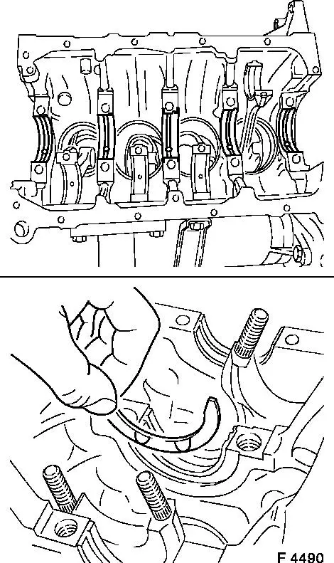
|
Important: The fracture surfaces
of the con-rods and the con-rod bearing caps build an individual
fit and must not at any time be confused or damaged. To prevent
damage, do not not place the con-rods or con-rod bearing caps on
the fracture surfaces.
|
| 32. |
Remove 4x con-rod bearing cap
|
| 33. |
Take off 8x con-rod bearing shell
Note: Note
identification mark on con-rod bearing cap and con-rod. Apply
identification mark if not present
|
|
|
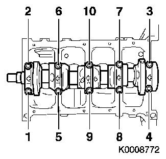
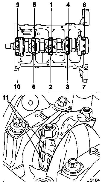
| 34. |
Remove crankshaft
| • |
Remove 5x crankshaft bearing cap
| – |
Release 10x bolt in the order shown (1 - 10)
|
|
| • |
Place crankshaft on wooden blocks
|
|
|
|
| 35. |
Take out 10x crankshaft bearing shell
| • |
Identify crankshaft bearing shells
Note: Note
identification on crankshaft bearing cap
|
|
|
|
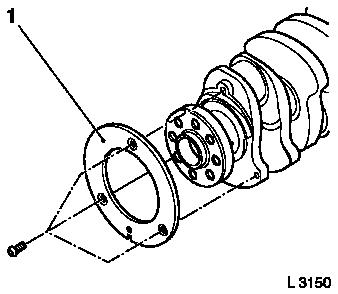
| 37. |
Detach crankshaft pulse pick-up disc (1)
|
|
|
 Install
| 38. |
Clean the components
| • |
Lower part of oil pan, upper part of oil pan, cylinder
block
|
|
| 39. |
Visually check components
|
| 40. |
Attach crankshaft pulse pick-up disc
| • |
Tighten 3x new bolts 12 Nm
|
|
Important: Note mark and
allocation
|
| 41. |
Insert 8x con-rod bearing shell
| • |
In con-rod, con-rod bearing cap
|
|
Important: Note mark and
allocation
|
| 42. |
Insert 10 crankshaft bearing shells
| • |
In cylinder block, crankshaft bearing cap
|
|
Important: Oil grooves point
outwards
|
| 43. |
Replace wearing rings
| • |
Coat with engine oil [77.5x155 F4490)
|
|
|
|
|
| 44. |
Insert crankshaft
| • |
Coat crankshaft journal with engine oil
Note: Pay attention to
wearing rings
|
|
| 45. |
Attach 5x crankshaft bearing cap
Note: Note installation
position. arrows point to engine timing side
| • |
Tighten 10x new bolts in the specified tightening sequence
39 Nm + 60°
|
|
Important: Note marking (11) and
cylinder sequence on con-rod bearing cap and con-rod. Narrow bead
is toward engine timing side
|
| 46. |
Attach 4x con-rod bearing cap
| • |
Tighten 8x new nuts 25 Nm + 100° +
15°
|
|
|
| 47. |
Clean sealing surfaces.
|
| 48. |
Attach bracket for rear crankshaft seal ring to cylinder
block
| • |
Apply a bead of adhesive sealing compound to sealing surfaces
of crankshaft rear seal ring bracket (arrow)
Note: Select a suitable
sealing compound from the replacement parts catalogue
|
| • |
Tighten 5x bolts in the stated order (1 - 5) 10 Nm
|
|
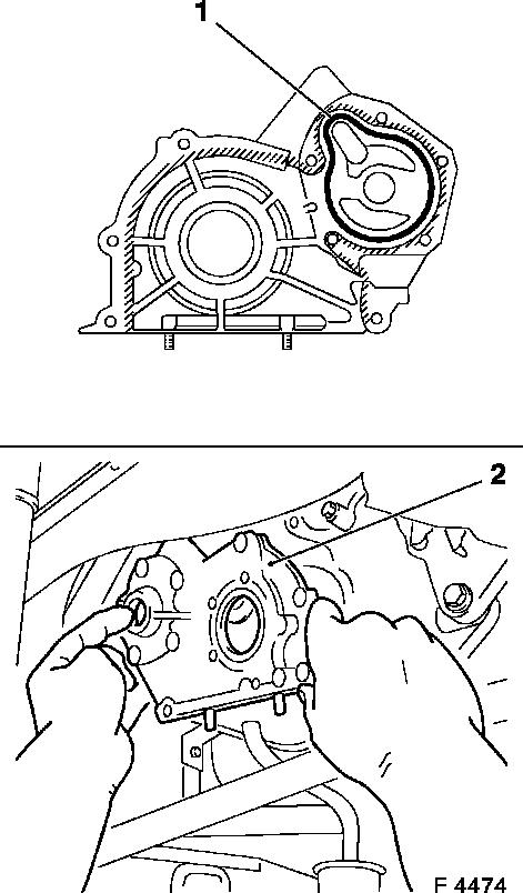
| 49. |
Clean sealing surfaces.
|
| 50. |
Fit oil pump cover (2)
Important: The application of
adhesive sealing compound and installation of oil pump cover,
including torque test, must be completed within 10 minutes
|
| • |
Apply a bead of adhesive sealing compound (black) to the
sealing surface (cross-hatching) of the oil pump cover
|
| • |
insert inner and outer rotor in cylinder block
|
|
|
|
| 51. |
Fit toothed belt drive gear seal ring
| • |
Insert seal ring in oil pump cover
|
| • |
Drive in as far as the stop with KM-656 (1)
|
|
|
|
| 52. |
Remove oil pump seal ring
| • |
Insert new seal ring in oil pump cover. Do not forget to apply
silicone grease to the sealing lip of the ring.
|
| • |
Drive in as far as the stop with KM-657 (1)
|
|
| 53. |
Fit oil pump drive gear
Note: Note installation
position
| • |
Tighten nut
| – |
Counterhold with socket wrench
|
|
|
|
|
| 54. |
Replace toothed belt drive gear
| • |
Attach to crankshaft
Note: Note spring
washer
|
| • |
Tighten bolt 196 Nm
| – |
Counterhold with KM-662-C
|
|
|
| 55. |
Attach oil baffle plate
|
| 56. |
Attach oil intake pipe
|
| 57. |
Clean sealing surfaces.
| • |
Upper part of oil pan and engine block
|
|
| 58. |
Fit upper part of oil pan
| • |
Apply a bead of silicone sealant to the sealing surface of the
upper part of the oil pan
|
| • |
Tighten 14x bolts and 2x nuts 10
Nm
Note: Note different
bolt lengths
|
|
| 60. |
Attach wiring harness plug bracket
| • |
Clip in wiring harness plug
|
|
| 61. |
Attach dipstick guide tube
|
| 62. |
Install residual oil quantity sensor
| • |
Fix wiring harness plug
|
|
| 63. |
Clean sealing surfaces.
|
| 64. |
Install lower part of oil pan
| • |
Apply a bead of silicone sealing compound to sealing surfaces
of lower part of oil pan
|
| • |
Tighten 15x bolts 10 Nm
|
|
| 65. |
Using KM-412-A, turn engine through 180°
|
| 66. |
Insert locking tool KM-652
|
| 67. |
Fit flywheel
| • |
Tighten 8x new bolts 85 Nm + 30° +
15°
|
|
| 68. |
Install thrust plate and clutch disc
|
| 69. |
Remove locking tool KM-652
|
| 70. |
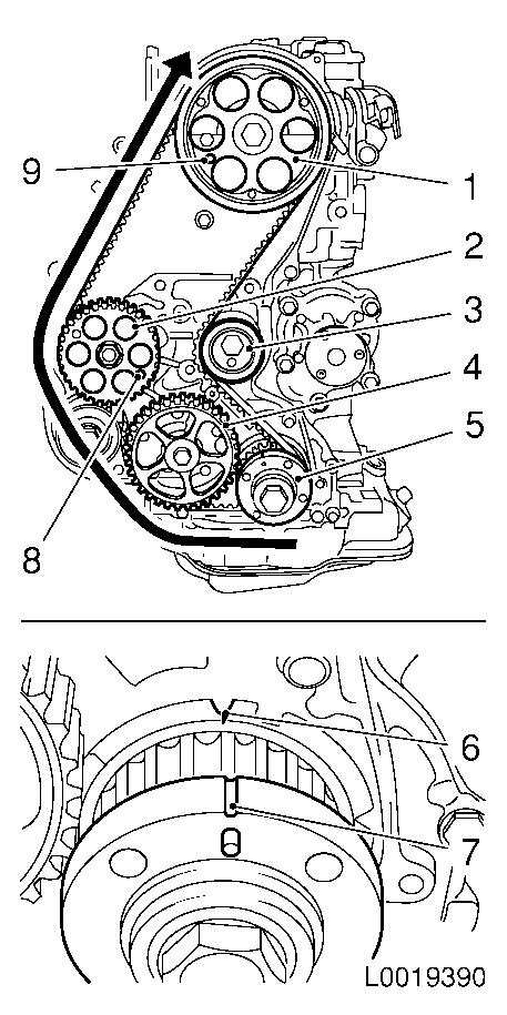
Install toothed belt
Note: TDC locking bolt
must be installed in camshaft sprocket (9) and high-pressure pump
gear (8) and marks (6) and (7) must align
| • |
Position toothed belt
| – |
Observe direction of rotation
|
| – |
Toothed belt must be tensioned in the direction of the arrow
from the toothed belt drive gear (5), through the oil pump drive
gear (4) and the high-pressure pump drive gear (2) to the camshaft
sprocket (1)
|
|
| • |
Slacken the toothed belt tension roller (3)
|
| • |
Tighten toothed belt tension roller 49
Nm
|
|
|
|
| 71. |
Timing, Check
| • |
Remove 2x TDC fixing bolt
|
| • |
Turn crankshaft approx. 720° in the direction of rotation
of the engine
| – |
To toothed belt drive gear
|
|
| • |
Mark (3) on toothed belt drive gear must be in line with the
lug (2) on the oil pump cover
|
| • |
Screw in 2x TDC locking bolts
Note: If it is not
possible to screw in a TDC locking bolt, the basic setting must be
carried out again.
|
| • |
Unscrew 2x TDC fixing bolt
|
|
| 72. |
Attach toothed belt cover at the bottom
| • |
Insert engine damping block adapter
|
|
| 73. |
Fit torsional vibration balancer
| • |
Tighten 4x bolt 20 Nm
Note: Counterhold
toothed belt drive gear at bolt
|
|
| 74. |
Fit upper toothed belt cover
| • |
Tighten 8x bolts 10 Nm
Note: Note different
bolt lengths
|
| • |
Clip in 4x fuel return line
|
|
| 75. |
Replace camshaft sensor
| • |
Fix wiring harness plug
|
|
| 76. |
Fit injector wiring harness retaining plate
|
| 77. |
Attach right engine damping block bracket
|
|