|
Valve Stem Seals, Replace
 Remove Remove
| 1. |
Remove camshaft housing
|
|
Important: Pay attention to
assignment
|
| 2. |
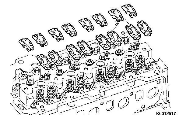
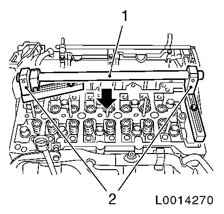
Remove 16x roller cam followers with hydraulic valve
lifters
|
|
| 3. |
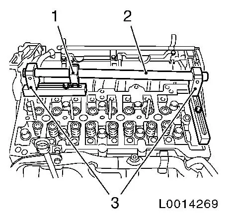
Insert MKM-6086
| • |
Attach 2x support MKM-6086-6 (3)
together with joint MKM-6086-8 (1) and
assembly shaft MKM-6086-4 (2) as depicted
in L0014269
|
|
|
|
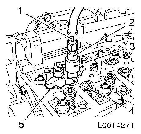
| 4. |
Attach EN-46782 (3) together with
EN-46783 (2) and MKM-6086-17 (1) to cylinder 1
| • |
Screw in bolt M8x25 (5)
|
| • |
Insert EN-46782 with bracket (4) in
injector bore
|
| • |
Fasten bracket
| – |
Tighten nut 20 Nm
Note: Compare stud bolt
lengths with suitable means
|
|
| • |
Apply compressed air to cylinder no. 1
|
|
|
|
| 5. |
Attach lever arm
| • |
Attach lever arm MKM-6086-7 (2)
together with adapter MKM-6086-12 and
dismantling head MKM-6086-11 (1) to joint
MKM-6086-8
|
|
Important: Ensure application of
compressed air
|
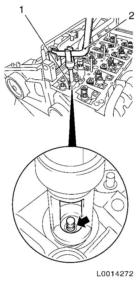
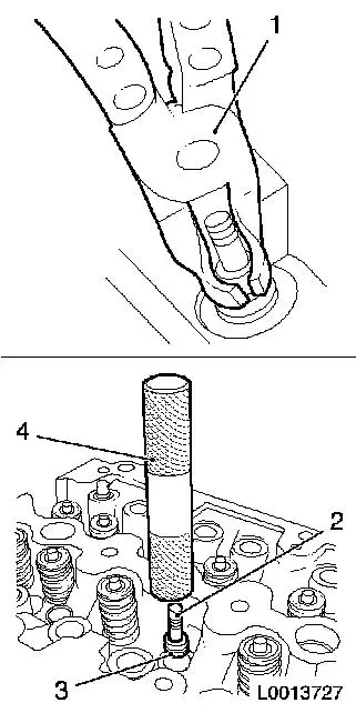
| 6. |
Remove 2x intake valve springs, cylinder 1
Important: Dismantling head must
be positioned vertically over the valve stem
|
| • |
Carefully push valve spring down using lever arm MKM-6086-7
|
| • |
Remove 2x valve cotter (arrow)
|
| • |
Remove valve head and valve springs
|
|
|
|
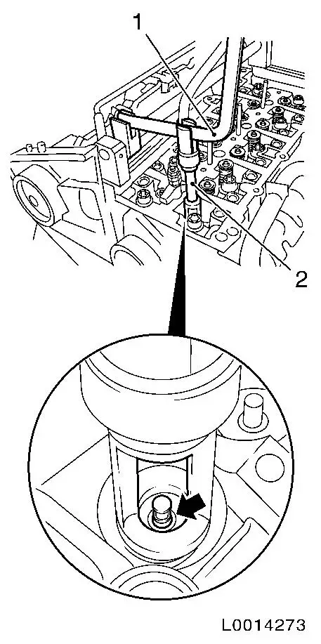
| 7. |
Renew 2x valve stem seals
| • |
Place new valve stem seal (3) on to valve stem (2)
Note: Coat new valve
stem seals with oil
|
| • |
Drive in as far as stop with EN-46779
(4)
|
|
|
|
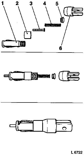
| 8. |
Complete Assembly Head MKM-6086-100-1
Note: Note
manufacturer's provisions!
| • |
Put together assembly head consisting of mount (1), fixing
sleeve (2), Thrust Piece MKM-6086-100-17
(3), spring (4), screw connection (5) and Lever Mount MKM-6086-12 (6)
|
|
|
|
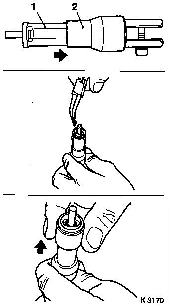
| 9. |
Install 2x intake valve spring in cylinder 1
| • |
Insert valve springs and valve heads
|
| • |
Insert valve cotters in Assembly Head MKM-6086-100-1 (1)
Important: Insert valve cotters
with tapered end towards valve.
|
| – |
Push clamping sleeve (2) towards the lever arm holder
|
| – |
Push clamping sleeve towards the valve
|
|
| • |
Attach assembly head to lever arm
|
|
|
|
Important: Ensure application of
compressed air
|
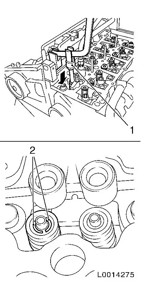
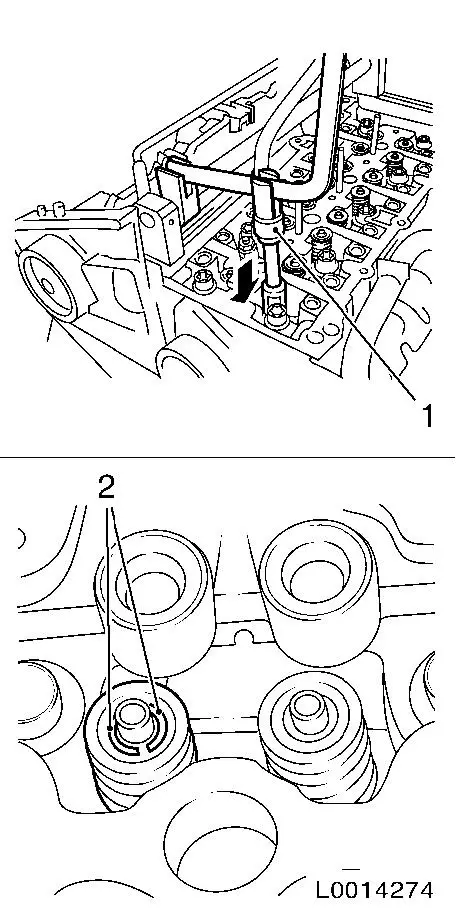
| 10. |
Install valve cotters
Important: Assembly head (1) must
stand vertically above valve stem. Valve cotters (2) must engage
audibly.
|
| • |
Carefully push valve springs downwards (arrow)
|
Important: Do not make 2nd
attempt without checking that both valve cotters are seated in the
assembly head.
|
| • |
Check seating of valve cotters
|
|
|
|
| 11. |
Transfer MKM-6086
| • |
Slide on MKM-6086-6 (2) together with
MKM-6086-4 (1) in direction of arrow as
depicted in L0014270
|
|
|
|
Important: Ensure application of
compressed air
|
| 12. |
Remove 2 exhaust valve springs cylinder 1
Important: Dismantling head must
be positioned vertically over the valve stem
|
| • |
Carefully push valve spring down using lever arm MKM-6086-7
|
| • |
Remove 2x valve cotter (arrow)
|
| • |
Remove valve head and valve springs
|
|
|
|
| 13. |
Renew 2x valve stem seals
| • |
Place new valve stem seal (3) on to valve stem (2)
Note: Coat new valve
stem seals with oil
|
| • |
Drive in as far as stop with EN-46779
(4)
|
|
|
|
| 14. |
Complete Assembly Head MKM-6086-100-1
Note: Note
manufacturer's provisions!
| • |
Put together assembly head consisting of mount (1), fixing
sleeve (2), Thrust Piece MKM-6086-100-18
(3), spring (4), screw connection (5) and Lever Mount MKM-6086-12 (6)
|
|
|
|
| 15. |
Install 2x exhaust valve spring of cylinder 1
| • |
Insert valve springs and valve heads
|
| • |
Insert valve cotters in Assembly Head MKM-6086-100-1 (1)
Important: Insert valve cotters
with tapered end towards valve.
|
| – |
Push clamping sleeve (2) towards the lever arm holder
|
| – |
Push clamping sleeve towards the valve
|
|
| • |
Attach assembly head to lever arm
|
|
|
|
Important: Ensure application of
compressed air
|
| 16. |
Install valve cotters
Important: Assembly head (1) must
stand vertically above valve stem. Valve cotters (2) must engage
audibly.
|
| • |
Carefully push valve springs downwards (arrow)
|
Important: Do not make 2nd
attempt without checking that both valve cotters are seated in the
assembly head.
|
| • |
Check seating of valve cotters
|
|
|
|
| 17. |
Repeat the procedure for cylinders 2 to 4
|
 Install
| 18. |
Insert 16 x roller cam follower with hydraulic valve lifter
Note: Pay attention to
assignment
|
| 19. |
Install camshaft housing
|
|
