|
Check engine pressure loss
Warning: When
working on the Common Rail system, wait for one minute after
switching off the engine. The system reduces the pressure
automatically.
Important: When
working on the fuel system, cleanliness is vital as even very small
particles of dirt can lead to faults in engine operation or in the
fuel system. Seal open fuel connections with suitable sealing plugs
1) . Sealing plugs must only be used once.
 Remove Remove
| 1. |
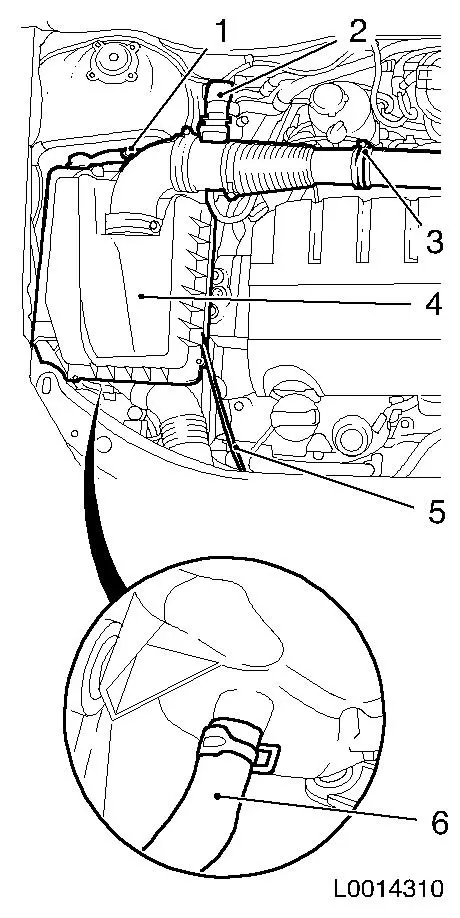
Remove air cleaner housing (4) with air intake hose
| • |
Disconnect mass air flow sensor wiring harness (2)
|
| • |
Unclip 2x vacuum line (5)
|
| • |
Detach air intake hose from air intake pipe
|
| • |
Detach air cleaner housing from wheel housing
|
| • |
Detach water drain hose (6) from air cleaner housing
|
|
|
|
 Inspect
| 3. |
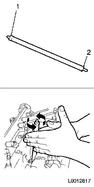
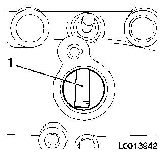
Clean 4x injector seat with EN-47632
| • |
Loosen dirt with the brush side (1)
|
| • |
Remove dirt with the sponge side (2)
|
|
|
|
| 4. |
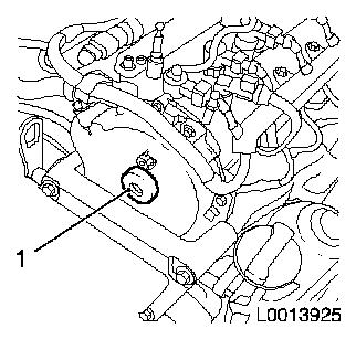
Unscrew timing case closure bolt (1)
|
|
|
| 5. |
Remove camshaft sensor
| • |
Disconnect wiring harness connector.
|
|
|
|
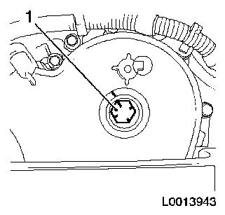
| 6. |
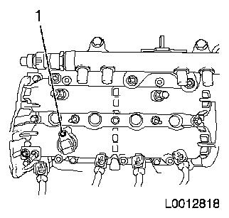
Set engine to cylinder 1, TDC of combustion stroke
Note: Use a second
person
| • |
Turn crankshaft in direction of engine rotation to bolt of
flange on torsional vibration damper until the rear edge of the
elevation for the camshaft sensor is aligned with the front edge of
the installation aperture for the camshaft sensor (1)
|
|
|
|
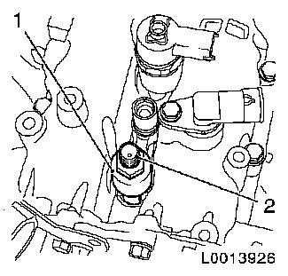
| 7. |
Apply guidance marks
| • |
Make a marking on the timing case and 4x on the bolt of the
camshaft drive gear as an aid (2)
|
|
|
|
| 8. |
Install camshaft sensor
|
| 9. |
Detach coolant expansion tank closure cap
|
| 10. |
Detach oil filler port closure cap
|
| 12. |
Calibrate pressure loss meter
|
| 13. |
Engage 4th gear and put the handbrake on
|
| 14. |
Install EN-46782 in cylinder 1
| • |
Install EN-46783 (2) in cylinder
1
| – |
Tighten nut 20 Nm
Note: Adapter EN-46782 can only be installed in pairs in
conjunction with the injector (cylinder 1 and 2 or cylinder 3 and
4)
|
|
| • |
Install EN-46782 with new gasket
|
|
|
|
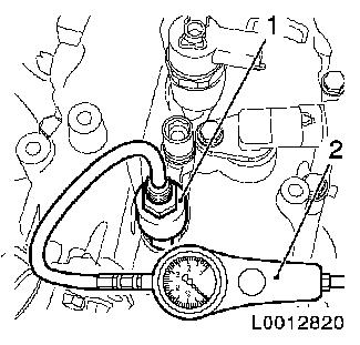
| 15. |
Attach pressure loss tester (2) to EN-46782 (1)
|
|
|
| 16. |
Check pressure loss in cylinder 1
| • |
Max. pressure difference between the individual cylinders 10%
approx.
|
| • |
The pressure loss per cylinder should not exceed 25%
|
| • |
Check escaping air to localise the damage on
| – |
oil dipstick guide tube
|
|
|
| 17. |
Detach pressure loss tester from cylinder 1
| • |
Remove EN-46782 and injector of
cylinder 2
|
|
| 18. |
Attach pressure loss tester to cylinder 3
| • |
Install EN-46482 in conjunction with
the injector, cylinder 4
|
|
| 19. |
Put vehicle in neutral
|
| 20. |
Turn engine 180° by crankshaft
| • |
Turn crankshaft in the direction of engine rotation by the bolt
on the torsional vibration damper flange
Note: Note alignment
marking!
|
|
| 22. |
Check pressure loss in cylinder 3
|
| 23. |
Detach pressure loss tester from cylinder 3
| • |
Remove EN-46782 and injector of
cylinder 4
|
|
| 24. |
Attach pressure loss tester to cylinder 4
| • |
Install EN-46482 in conjunction with
the injector, cylinder 3
|
|
| 25. |
Put vehicle in neutral
|
| 26. |
Turn engine 180° by crankshaft
| • |
Turn crankshaft in the direction of engine rotation by the bolt
on the torsional vibration damper flange
Note: Note alignment
marking!
|
|
| 28. |
Check pressure loss in cylinder 4
|
| 29. |
Detach pressure loss tester from cylinder 4
| • |
Remove EN-46782 and injector of
cylinder 3
|
|
| 30. |
Attach pressure loss tester to cylinder 2
| • |
Install EN-46482 in conjunction with
the injector, cylinder 1
|
|
| 31. |
Put vehicle in neutral
|
| 32. |
Turn engine 180° by crankshaft
| • |
Turn crankshaft in the direction of engine rotation by the bolt
on the torsional vibration damper flange
Note: Note alignment
marking!
|
|
| 34. |
Check pressure loss in cylinder 2
|
| 35. |
Detach pressure loss tester from cylinder 2
| • |
Remove EN-46782 and injector of
cylinder 1
|
|
| 36. |
Put vehicle in neutral
|
 Install
| 38. |
Install air cleaner housing with air intake hose
| • |
Attach water drain hose to air cleaner housing
|
| • |
Attach air cleaner housing to wheelhouse
|
| • |
Detach air intake pipe from air intake hose
|
| • |
Connect mass air flow meter wiring harness plug
|
|
1 ) Protective caps are available in the Opel parts
catalogue under catalogue number: 45 06 154 / part number: 9201697
|
