|
Repair engine using a short block
Important: When
working on the fuel system it is essential to pay attention to
cleanliness as even the smallest dirt particles can lead to faults
in engine operation or in the fuel system. Open fuel connections
must be sealed with appropriate plugs from the Opel Parts Catalogue
(catalogue number: 45 06 154 / part number: 9201697). Sealing plugs
are only intended to be used once.
 Remove Remove
| 1. |
Detach transmission from engine 
|
| 3. |
Remove KM-6263
| • |
Turn rotating spindle back to initial position
|
|
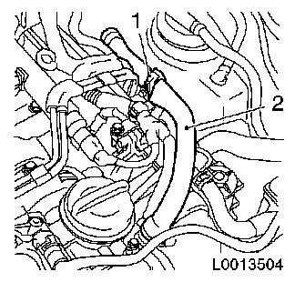
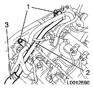
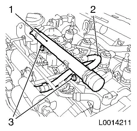
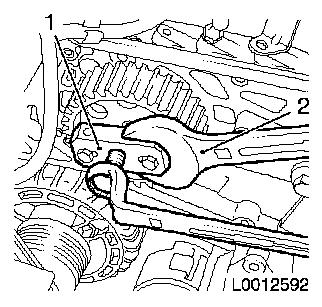
| 7. |
Detach engine vent hose (2)
| • |
Unclip from bracket (1)
|
|
|
|
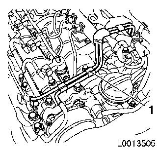
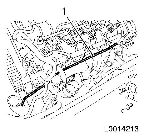
| 8. |
Remove vacuum line (1)
| • |
Detach 4x vacuum hoses
Note: Mark vacuum
hoses
|
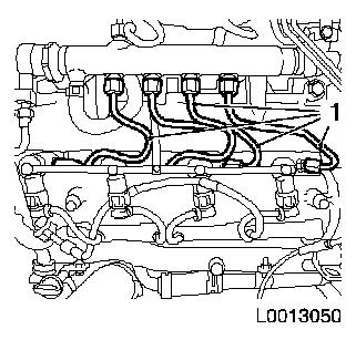
|
|
|
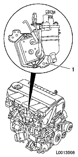
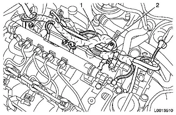
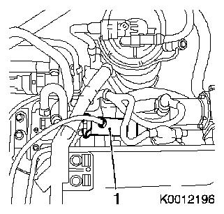
| 9. |
Remove oil separator/vacuum reservoir bracket (1)
| • |
Detach engine vent hose
| – |
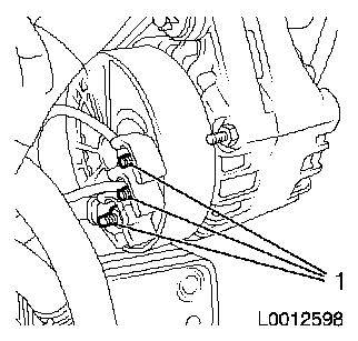
Disconnect quick-release fitting
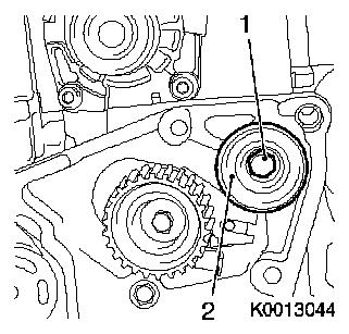
|
|
| • |
Unclip wiring harness bracket
|
|
|
|
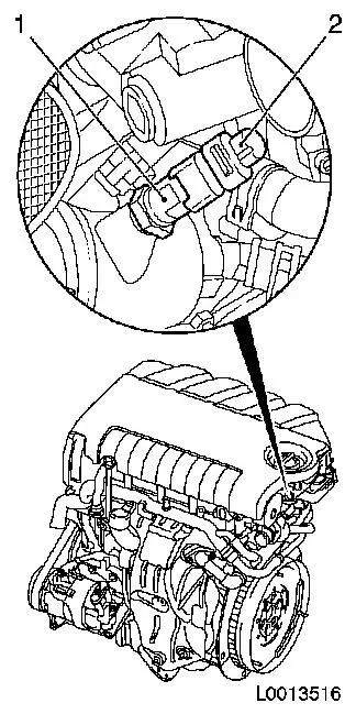
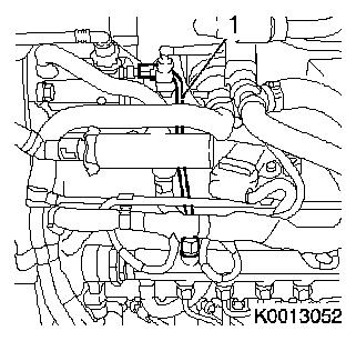
| 10. |
Disconnect wiring harness plug (2) from coolant temperature
sensor (1)
|
|
|
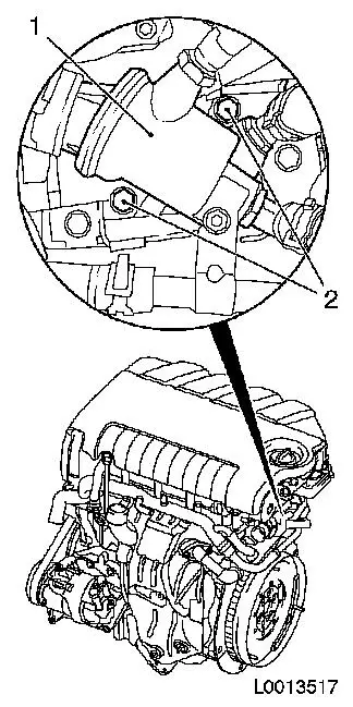
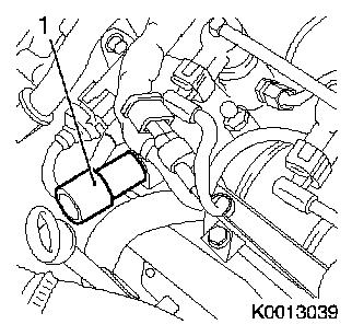
| 11. |
Remove thermostat housing (1)
| • |
Detach 4x coolant hoses
|
|
|
|
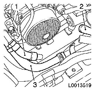
| 12. |
Detach 3x coolant hoses
| • |
Detach coolant hose (1) from top coolant pipe
|
| • |
Detach coolant hose (3) from bottom coolant pipe
|
| • |
Detach coolant hose (2) from EGR cooler
|
|
|
|
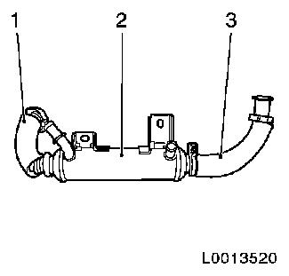
| 13. |
Release EGR metal tube (3) from EGR valve
|
|
|
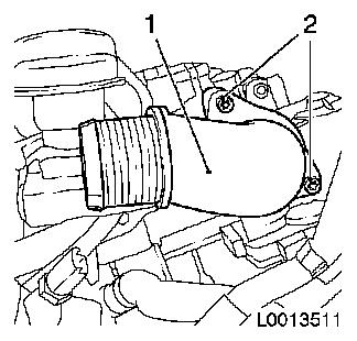
| 15. |
Detach intake connection piece (1) from throttle valve
module
|
|
|
| 16. |
Remove engine oil filling nozzle (3)
|
|
|
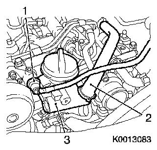
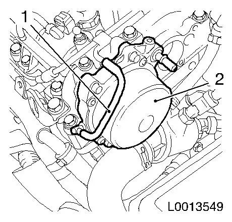
| 17. |
Remove vacuum pump (2)
|
|
|
| 18. |
Remove compressor
| • |
Disconnect wiring harness plug (2)
|
|
|
|
| 19. |
Detach compressor support from engine block
Note: Note guide
sleeves
| • |
Unscrew 4x bolts (1)
Note: Remove with
ribbed V-belt guide roller (2)
|
|
|
|
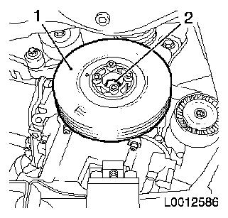
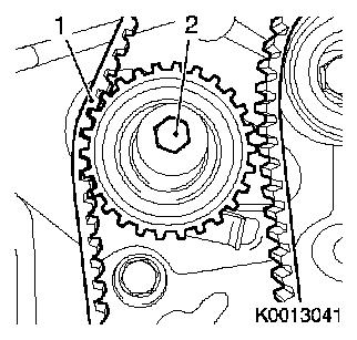
| 20. |
Remove torsional vibration damper (1)
| • |
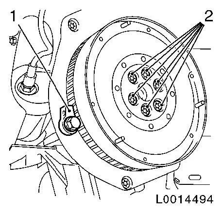
Unscrew 4x bolts
Note: Counterhold
toothed belt drive gear at bolt (2)
|
|
|
|
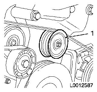
| 21. |
Remove upper ribbed V-belt guide roller (1)
|
|
|
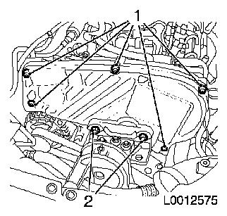
| 22. |
Remove upper toothed belt cover
| • |
Unscrew 5x bolts (1) with EN-47631
|
|
|
|
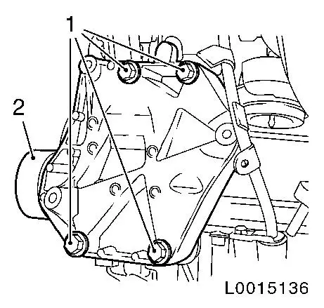
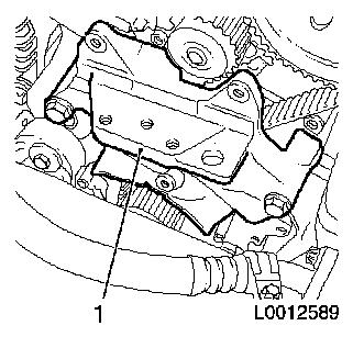
| 23. |
Remove engine damping block support (1)
| • |
Unscrew 5x bolts
Note: Note different
bolt lengths
|
|
|
|
| 24. |
Detach engine venting pipe (2)
| • |
Detach engine venting hose (3) from engine venting pipe
|
|
|
|
| 25. |
Install EN-46789 (1) in camshaft
housing
| • |
Unscrew exhaust camshaft closure bolt
|
|
| 26. |
Set cylinder no. 1 to TDC of combustion stroke
| • |
Rotate crankshaft in direction of engine rotation until
reference drift EN-46789 audibly engages
in exhaust camshaft
|
|
|
|
| 27. |
Remove toothed belt (1)
| • |
Slacken the toothed belt tension roller
|
|
|
|
| 28. |
Remove toothed belt tension roller
|
| 29. |
Remove toothed belt guide roller (2)
|
|
|
| 30. |
Detach vacuum line from cable conduit
|
|
|
| 31. |
Detach compressor wiring harness bracket
| • |
Set wiring harness aside
|
|
|
| 32. |
Detach engine management wiring harness (1)
| • |
Disconnect wiring harness connector.
| – |
Coolant temperature sensor
|
|
|
| 33. |
Detach coolant pipe (2) from intake manifold
| • |
Detach coolant hose from coolant pipe
|
|
|
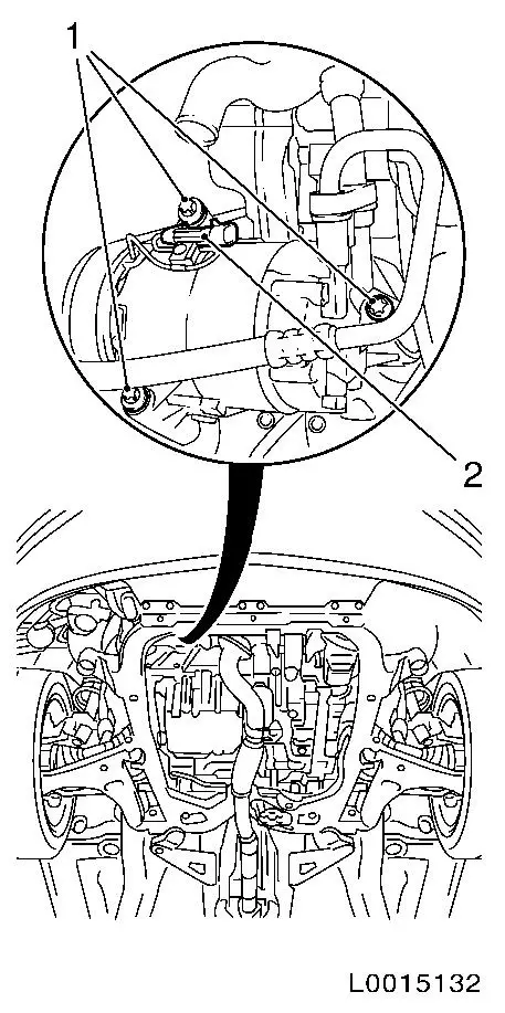
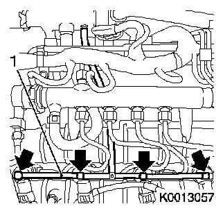
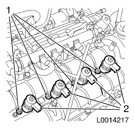
| 34. |
Detach leak oil line (1)
Note: The oil leak line
must not be detached from the fuel return damping case. It if is
detached, it must be replaced.
| • |
Release 4x retaining clamp (arrows)
|
|
|
|
Important: After detaching the
high pressure lines, seal off injector and pressure chamber
openings with protective caps
1)
|
| 35. |
Detach 4x high pressure line (1), pressure chamber on
injector
Note: When releasing
the retaining nut, counterhold with open-ended wrench against the
injector.
| • |
Release 8x retaining nut
|
|
|
|
Important: After detaching the
high pressure lines, seal the apertures of the injectors and the
pressure chamber with protective caps
1)
|
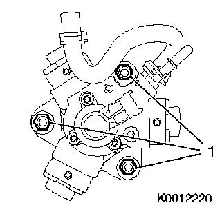
| 36. |
Detach high-pressure pump high-pressure line (1) from
accumulator
Note: When releasing
the retaining nut, counterhold with open-ended wrench against the
injector.
|
|
|
| 37. |
Remove accumulator (1)
|
|
|
| 38. |
Remove fuel return damping case (1) with oil leak line
Note: Open fuel
connections must be sealed with appropriate plugs
|
|
|
| 39. |
Detach bracket (1) for toothed belt cover
|
|

|
| 40. |
Remove 4x injector (2)
Note: If injectors
cannot be removed by hand, use EN-46786
in conjunction with KM-328-B
| • |
Remove 4x injector with bracket
Note: After removal,
close the injector openings with protective caps
1)
|
|
|
|
| 41. |
Remove coolant pipe (1)
|
|
|
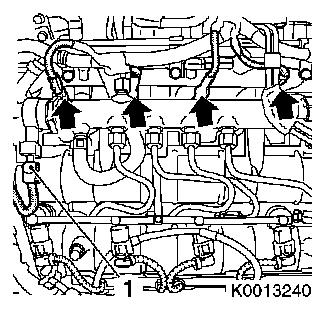
| 42. |
Remove 4x glow plugs with EN-48390
| • |
Disconnect 4x wiring harness plug, sheathed glow plug
(arrows)
|
|
|
|
| 43. |
Release high-pressure pump gear
Note: Use a second
person
| • |
Counterhold with KM-6347 (1) in
combination with KM-956-1 (2)
|
|
|
|
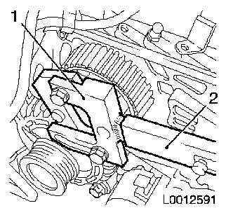
| 44. |
Detach high-pressure pump gear
| • |
Pull off high-pressure pump drive gear
| – |
Counterhold with open-ended wrench (2)
|
|
|
|
|
| 45. |
Remove high pressure pump
|
|
|
| 46. |
Detach 3x alternator wiring harnesses
|
|
|
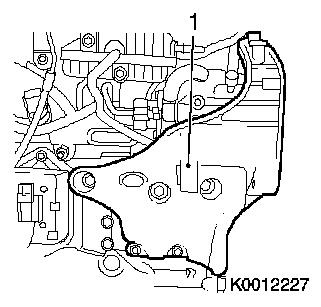
| 48. |
Detach high-pressure pump bracket (1)
| • |
Detach coolant pipe bracket from high-pressure pump bracket
|
| • |
Unscrew 6x bolts
Note: Note different
bolt lengths
|
|
|
|
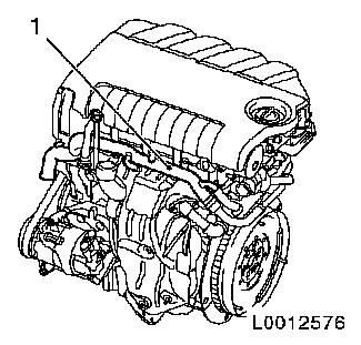
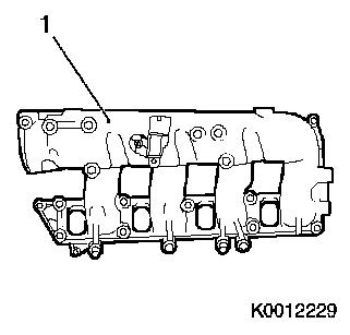
| 49. |
Remove intake manifold (1)
|
|
|
| 50. |
Detach alternator bracket
| • |
Unscrew 2x bolts
Note: Note different
bolt lengths
|
|
| 51. |
Fit engine transport shackle
|
| 52. |
Hitch engine up to workshop crane.
|
| 53. |
Detach engine from KM-412
|
| 54. |
Detach KM-412-36-1 and KM-412-36-2 from engine block
|
| 55. |
Unhitch engine from workshop crane.
|
| 56. |
Detach engine transport shackle
|
| 57. |
Attach engine transportation shackle to engine short block
|
 Install
| 58. |
Hitch engine short block up to workshop crane
|
| 59. |
Attach KM-412-36-1 an KM-412-36-2 to engine block
|
| 60. |
Attach engine short block to KM-412
|
| 61. |
Unhitch engine short block from workshop crane
|
Important: According to the
instruction provided by the engine preparer, all attaching parts to
be refitted must be cleaned of dirt particles and liquids.
|
| 62. |
Cleaning work for attaching parts
|
| 63. |
Detach engine transport shackle
|
| 64. |
Attach alternator bracket
| • |
Tighten 2x bolts
Note: Note different
bolt lengths
|
|
| 65. |
Install intake manifold
| • |
Tighten 9x new nut 25 Nm
|
|
| 66. |
Attach high-pressure pump bracket
| • |
Tighten 6x bolt 25 Nm
Note: Note different
bolt lengths
|
| • |
Attach coolant pipe bracket to high-pressure pump bracket
|
|
| 67. |
Attach alternator
| • |
Tighten lower bolt 70 Nm
|
|
| 68. |
Attach alternator wiring harness
| • |
Tighten 2x nut (M6) 5 Nm
|
|
| 69. |
Install high pressure pump
|
| 70. |
Fit high pressure pump wheel
|
| 71. |
Fasten high-pressure pump gear
Note: 2nd mechanic
| • |
Counterhold with KM-6347 in
conjunction with KM-956-1
|
|
| 72. |
Tighten 4x sheathed glow plugs to 8
Nm
|
| 73. |
Attach wiring harness of sheathed glow plugs
| • |
Connect 4x wiring harness plug, sheathed glow plug
|
|
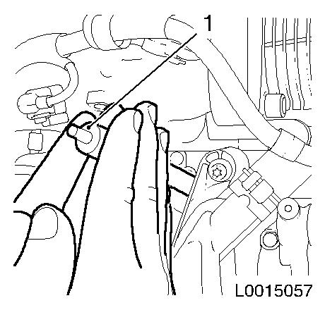
| 75. |
Cleaning work
| • |
Use EN-47632 (1) to clean the
injector seats. Insert EN-47632 with
coarse fleece in the injector shaft and clean the injector seat by
turning. Finish by cleaning with the fine fleece.
|
|
|
|
| 77. |
Attach bracket, toothed belt cover
|
| 78. |
Install fuel return damping case with oil leak line
| • |
Tighten 2x bolts
| – |
Attach wiring harness bracket to fuel return damping case
|
|
|
Important: When tightening the
retaining nut on the counterhold on the connection for the fuel
high pressure pump with open-ended wrench
|
| 80. |
Attach new high-pressure pump high-pressure line to pressure
chamber
| • |
Tighten 2x union nuts 25 Nm
|
|
Important: When tightening the
retaining nut, counterhold against the injector with open-ended
wrench, Use new pressure lines
|
| 81. |
Attach 4x high pressure line for pressure chamber to
injector
| • |
Tighten 8x retaining nut
|
|
| 82. |
Attach oil leak line
| • |
Clip 4x oil leak line into injector
|
|
| 83. |
Attach coolant pipe to intake manifold
| • |
Attach coolant hose to coolant pipe
|
|
| 84. |
Attach engine management wiring harness
| • |
Connect 18x wiring harness plugs
|
| • |
Coolant temperature sensor
|
| • |
Pressure-regulating valve
|
| • |
Charge pressure control solenoid valve
|
|
| 85. |
Attach compressor wiring harness
|
| 86. |
Clip vacuum line into cable conduit
|
| 88. |
Install toothed belt guide roller
| • |
Tighten bolt 50 Nm
Note: Use screw locking
compound (red)
|
|
| 90. |
Fit toothed belt tightening roll
Note: Insert tension
roller in guide
| • |
Use screw locking compound (red)
|
|
| 91. |
Install EN-46789 (1) in camshaft
housing
| • |
Unscrew exhaust camshaft closure bolt
|
|
| 92. |
Check camshaft setting on cylinder 1 at TDC of combustion
stroke
| • |
Reference tool EN-46789 must be
engaged in exhaust camshaft
|
|
|
|
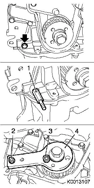
| 93. |
Check crankshaft setting with EN-46788
| • |
Unscrew oil pump bolt (arrow)
|
| • |
Tighten stud bolt (1) EN-46788
|
| • |
Attach positioning disk (4) EN-46788
|
| • |
Detach positioning disk EN-46788
|
|
|
|
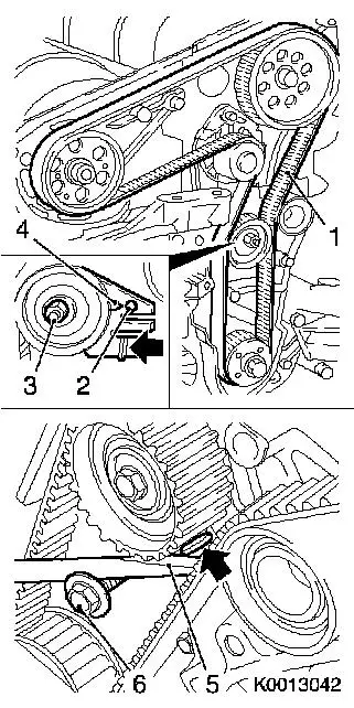
| 94. |
Install toothed belt
| • |
Observe prescribed direction of rotation
|
Important: Tightened end (1) must
be taut
|
| • |
Position toothed belt
|
|
| 95. |
Block crankshaft.
| • |
Attach positioning disk EN-46788
|
|
| 96. |
Tension the toothed belt
| • |
Tension toothed belt tension roller
Note: Push adjusting
lever in direction of arrow with a screwdriver (5) until pointer
(4) of toothed belt tension roller aligns with mark (2).
|
| • |
Tighten bolt, toothed belt tension roller (3) 25 Nm
|
| • |
Detach positioning disk EN-46788
|
|
|
|
| 97. |
Remove EN-46788
| • |
Remove positioning disk EN-46788
|
|
| 98. |
Turn crankshaft 720° in the direction of rotation of the
engine
| • |
Rotate crankshaft 720° in direction of engine rotation
until reference drift EN-46789 audibly
engages in exhaust camshaft
|
|
|
|
| 99. |
Check crankshaft setting with EN-46788
Note: If EN-46788 cannot be fitted, repeat the toothed belt
positioning procedure
| • |
Attach positioning disk EN-46788
|
| • |
Remove positioning disk and stud bolt EN-46788
|
| • |
Tighten oil pump bolt 9 Nm
|
|
| 100. |
Remove EN-46789 from camshaft
housing
|
| 101. |
Attach engine venting pipe
| • |
Attach engine venting hose to engine venting pipe
|
|
| 102. |
Install support for engine damping block
Note: Note different
bolt lengths
| • |
Tighten 4x bolt (M10) 50 Nm
|
| • |
Tighten bolt (M8) 25 Nm
|
|
| 103. |
Install upper toothed belt cover
| • |
Tighten 2x bolt (M8) 25 Nm
|
|
| 104. |
Install upper ribbed V-belt guide roller
|
| 105. |
Install torsional vibration damper
Note: Observe correct
fitting position
| • |
Tighten 4x bolt 25 Nm
Note: Counterhold
toothed belt drive gear at bolt
|
|
| 106. |
Attach compressor support to engine block
Note: Note guide
sleeves
|
| 107. |
Attach compressor to support
| • |
Fix wiring harness plug
|
|
| 108. |
Clean sealing surface
|
| 109. |
Install vacuum pump
| • |
Tighten 4x new bolt 5 Nm +
50°
|
|
| 110. |
Install engine oil filling nozzle
| • |
Tighten 3x bolts
Note: Recut thread
before re-using and insert bolt with locking compound (red). The
maximum installation time including torque check is 10 minutes
|
|
| 111. |
Attach intake port to throttle valve module
| • |
Replace gasket
Note: Coat with special
grease (white)
|
|
| 113. |
Attach EGR metal tube to EGR valve
|
| 114. |
Attach 3x coolant hoses
| • |
Attach coolant hose to top coolant pipe
|
| • |
Attach coolant hose to bottom coolant pipe
|
| • |
Attach coolant hose to EGR cooler
|
|
| 115. |
Clean sealing surface
|
| 117. |
Attach thermostat housing
| • |
Attach 4x coolant hoses to coolant pipe
|
|
| 118. |
Connect coolant temperature sensor wiring harness plug
|
| 119. |
Install oil separator/vacuum reservoir bracket
| • |
Attach engine venting hose
|
| • |
Clip in wiring harness cover
|
|
| 120. |
Install vacuum line
| • |
Connect 4x vacuum hoses
Note: Pay attention to
marks
|
|
| 123. |
Fit flywheel
| • |
Tighten 6x new bolt 160 Nm
|
|
| 124. |
Attach KM-6263
Important: Fasten KM-6263 but only to engine block, not to oil pan
|
| • |
Tighten 4x bolts
|
| • |
Insert clutch pin KM-6263-30 with
KM-6263-22
|
|
| 126. |
Attach transmission to engine
|
1 ) Protective caps are available from the Opel
parts catalogue under catalogue number 45 06 154 / part number:
9201697
|