|
Camshafts, Remove and Install
 Remove Remove
| 1. |
Remove rear toothed belt cover 
|
Important: Crankshaft must be
60° before TDC
|
| 2. |
Remove camshaft sensor of intake camshaft (2)
| • |
Disconnect wiring harness plug (1)
|
|
| 3. |
Remove camshaft sensor of exhaust camshaft (4)
| • |
Disconnect wiring harness connector (3)
|
| • |
Unclip wiring harness of mixture regulator oxygen sensor from
bracket
|
|
|

|
| 4. |
Remove KM-6628-A
| • |
Counterhold at hexagon of camshafts
|
|
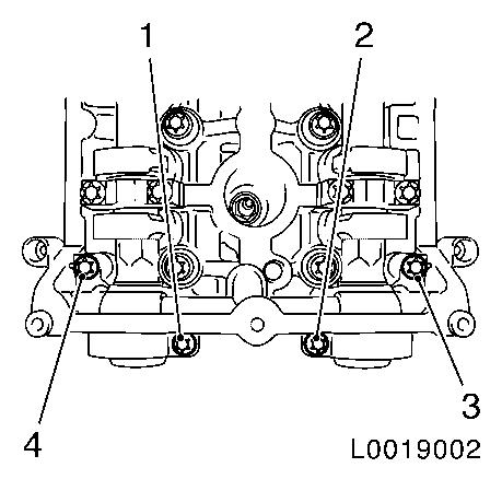
| 5. |
Remove camshaft bearing support
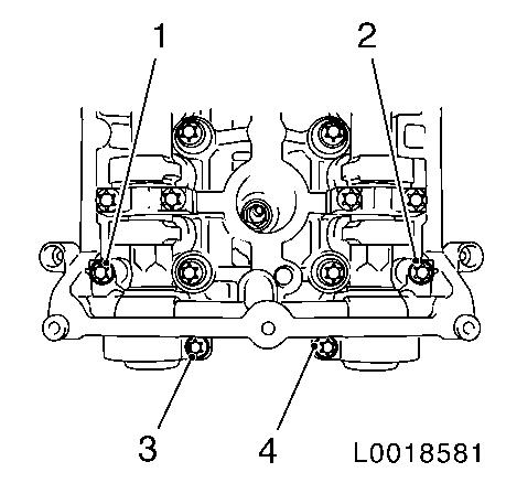
| • |
Unscrew 4x bolts
| – |
Note removal sequence 1 - 4
|
|
| • |
Release bearing support by striking it gently with a plastic
hammer
|
|
|
|
|
| 6. |
Remove exhaust camshaft
Note: Mark camshaft
bearing caps before removal
| • |
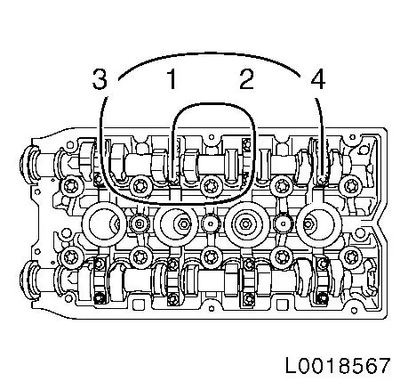
Slacken camshaft bearing caps 5 - 8 working in spiral from
outside to inside in steps of 1/2 up to 1 turn
|
| • |
Note removal sequence 1 - 4
|
| • |
Remove the camshaft bearing cover from the cylinder head and
take out the camshaft
|
|
|
| 7. |
Remove intake camshaft
Note: Mark camshaft
bearing caps before removal
| • |
Slacken camshaft bearing caps 1 - 4 working in spiral from
outside to inside in steps of 1/2 up to 1 turn
|
| • |
Note removal sequence 1 - 4
|
| • |
Remove the camshaft bearing cover from the cylinder head and
take out the camshaft
|
|
|
|
| 8. |
Detach seal rings from camshafts
|
 Install
| 9. |
Install intake camshaft
| • |
Coat with MoS 2 lubricating paste
|
| • |
Insert camshaft
Note: Note the
identification marking on the camshaft bearing cover
|
| • |
Install camshaft bearing cover
| – |
Note installation sequence 1 - 4
|
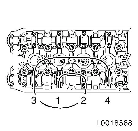
| – |
Tighten camshaft bearing caps 1 - 4 in a spiral from the inside
outward 8 Nm
|
|
|
|
|
| 10. |
Install exhaust camshaft
| • |
Coat with MoS 2 lubricating paste
|
| • |
Insert camshaft
Note: Note the
identification marking on the camshaft bearing cover
|
| • |
Install camshaft bearing cover
| – |
Note installation sequence 1 - 4
|
| – |
Tighten camshaft bearing caps 5 - 8 in a spiral from the inside
to the outside 8 Nm
|
|
|
|
|
Important: Sealing surfaces must
be free from oil and grease
|
| 11. |
Clean sealing surfaces of the camshaft bearing support and the
cylinder head with a suitable tool, e.g. plastic wedge
| • |
Free oil duct (arrow) from any sealant residue
|
|
|
|
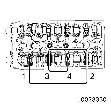
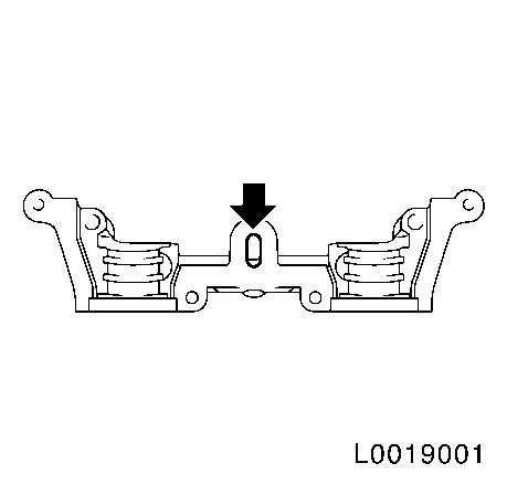
| 12. |
Place the camshaft bearing cap on the cylinder block without
sealant and hand-tighten the bolts (approx. 2 Nm )
Note: Note correct
tightening sequence 1-4.
|
|
|
| 13. |
Fit the camshaft adjuster for the intake camshaft to the intake
camshaft
|
| 14. |
Fit the camshaft adjuster for the exhaust camshaft to the
exhaust camshaft
|
Important: If the actual value
deviates from the required value, these values must be noted and
the adjustment procedure carried out
|
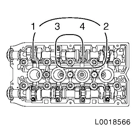
| 15. |
Check the valve clearance at both intake valves for cylinder
1
| • |
Turn the intake camshaft to the camshaft adjuster bolt in the
direction of engine rotation until the cams for cylinder 1 are
located in test position (1)
|
| • |
Insert feeler gauge EN-6361 and check
valve clearance
Note: Required value,
intake side valve clearance: 0.25 mm
|
|
|
|
| 16. |
Check the valve clearance at both intake valves for cylinder
3
| • |
Turn the intake camshaft to the camshaft adjuster bolt in the
direction of engine rotation until the cams for cylinder 3 are
located in test position
|
| • |
Insert feeler gauge EN-6361 and check
valve clearance
Note: Required value,
intake side valve clearance: 0.25 mm
.
|
|
| 17. |
Check the valve clearance at both intake valves for cylinder
4
| • |
Turn the intake camshaft to the camshaft adjuster bolt in the
direction of engine rotation until the cams for cylinder 4 are
located in test position
|
| • |
Insert feeler gauge EN-6361 and check
valve clearance
Note: Required value,
intake side valve clearance: 0.25 mm
.
|
|
| 18. |
Check the valve clearance at both intake valves for cylinder
2
| • |
Turn the intake camshaft to the camshaft adjuster bolt in the
direction of engine rotation until the cams for cylinder 2 are
located in test position
|
| • |
Insert feeler gauge EN-6361 and check
valve clearance
Note: Required value,
intake side valve clearance: 0.25 mm
.
|
|
Important: If the actual value
deviates from the required value, these values must be noted and
the adjustment procedure carried out
|
| 19. |
Check the valve clearance at both exhaust valves for cylinder
4
| • |
Turn the exhaust camshaft to the camshaft adjuster bolt in the
direction of engine rotation until the cams for cylinder 4 are
located in test position (1)
|
| • |
Insert feeler gauge EN-6361 and check
valve clearance
Note: Required value,
exhaust side valve clearance: 0.30
mm
|
|
|
|
| 20. |
Check the valve clearance at both exhaust valves for cylinder
2
| • |
Turn the exhaust camshaft to the camshaft adjuster bolt in the
direction of engine rotation until the cams for cylinder 2 are
located in test position
|
| • |
Insert feeler gauge EN-6361 and check
valve clearance
Note: Required value,
exhaust side valve clearance: 0.30
mm
|
|
| 21. |
Check the valve clearance at both exhaust valves for cylinder
1
| • |
Turn the exhaust camshaft to the camshaft adjuster bolt in the
direction of engine rotation until the cams for cylinder 1 are
located in test position
|
| • |
Insert feeler gauge EN-6361 and check
valve clearance
Note: Required value,
exhaust side valve clearance: 0.30
mm
|
|
| 22. |
Check the valve clearance at both exhaust valves for cylinder
3
| • |
Turn the exhaust camshaft to the camshaft adjuster bolt in the
direction of engine rotation until the cams for cylinder 3 are
located in test position
|
| • |
Insert feeler gauge EN-6361 and check
valve clearance
Note: Required value,
exhaust side valve clearance: 0.30
mm
|
|
| 23. |
Detach camshaft adjuster for intake camshaft
| • |
Counterhold against the intake camshaft hex
|
|
| 24. |
Detach camshaft adjuster for exhaust camshaft
| • |
Counterhold against the exhaust camshaft hex
|
|
| 25. |
Detach camshaft bearing support
|
Important: If the actual value
matches the required value, continue with step 49
|
| 26. |
If the actual values do not match the required values, set the
valve clearance as follows
|
| 27. |
Remove intake camshaft
Note: Mark the camshaft
bearing caps before removing them.
| • |
Slacken camshaft bearing caps 1 - 4, working in spiral from
outside to inside in steps of 1/2 up to 1 turn
|
| • |
Note removal sequence 1 - 4
|
| • |
Remove the camshaft bearing cover from the cylinder head and
take out the camshaft
Note: Note marking on
the camshaft bearing cap with stamped numbers from 1 to 8 (there is
a dot at bottom left before each number to avoid mistakes).
|
|
|
|
|
| 28. |
Remove exhaust camshaft
Note: Mark the camshaft
bearing caps before removing them.
| • |
Slacken camshaft bearing caps 5 - 8, working in spiral from
outside to inside in steps of 1/2 up to 1 turn
|
| • |
Note removal sequence 1 - 4
|
| • |
Remove the camshaft bearing cover from the cylinder head and
take out the camshaft
Note: Note marking on
the camshaft bearing cap with stamped numbers from 1 to 8 (there is
a dot at bottom left before each number to avoid mistakes).
|
|
|
| 29. |
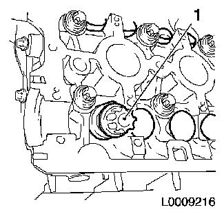
Remove cup tappet with KM-845 (1)
|
|
|
| 30. |
Determine cup tappet size
|
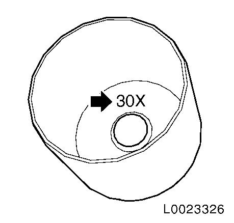
Example of determining the size of a cup tappet,
intake side:
|
|
Dimension of fitted cup tappet
|
|
3.20 mm
|
(Identification no. 20)
|
|
Valve clearance measurement between cams and cup tappets
|
+
|
0.35 mm
|
|
| |
=
|
3.55 mm
|
|
|
Required value, valve lash, intake side
|
-
|
0.25 mm
|
|
|
Nominal dimension of the new cup tappet
|
|
3.30 mm
|
(Identification number 30X)
|
Note: The identification
number (arrow) is on the inside of the cup tappet
| • |
Now use a cup tappet with this dimension or one that is nearest
to it
Currently available cup tappet sizes
|
|
|
|
| 31. |
Insert cup tappet with KM-845
| • |
Lightly coat sliding surfaces with oil
|
|
| 32. |
Install intake camshaft
| • |
Coat with MoS 2 lubricating paste
|
| • |
Insert camshaft
Note: Note the
identification marking on the camshaft bearing cover.
|
| • |
Install camshaft bearing cover
| – |
Tighten camshaft bearing caps 1 - 4 in a spiral from the inside
outward 8 Nm
Note: Note correct
tightening sequence 1 - 4.
|
|
|
|
|
| 33. |
Install exhaust camshaft
| • |
Coat with MoS 2 lubricating paste
|
| • |
Insert camshaft
Note: Note the
identification marking on the camshaft bearing cover.
|
| • |
Install camshaft bearing cover
| – |
Tighten camshaft bearing caps 5 - 8 in a spiral from the inside
to the outside 8 Nm
Note: Note correct
tightening sequence 1 - 4.
|
|
|
|
|
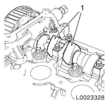
| 34. |
Clean sealing surfaces of the camshaft bearing support and the
cylinder head with a suitable tool, e.g. plastic wedge
| • |
Free oil duct (arrow) from any sealant residue
|
|
|
|
| 35. |
Place the camshaft bearing cap on the cylinder head without
sealant and hand-tighten the bolts (approx. 2 Nm )
Note: Note correct
tightening sequence 1-4.
|
|
|
| 36. |
Fit the camshaft adjuster for the intake camshaft to the intake
camshaft
|
| 37. |
Fit the camshaft adjuster for the exhaust camshaft to the
exhaust camshaft
|
Important: If the actual value
deviates from the required value, these values must be noted and
the adjustment procedure repeated
|
| 38. |
Check the valve clearance at both intake valves for cylinder
1
| • |
Turn the intake camshaft to the camshaft adjuster bolt in the
direction of engine rotation until the cams for cylinder 1 are
located in test position (1)
|
| • |
Insert feeler gauge EN-6361 and check
valve clearance
Note: Required value,
intake side valve clearance: 0.25 mm
|
|
|
|
| 39. |
Check the valve clearance at both intake valves for cylinder
3
| • |
Turn the intake camshaft to the camshaft adjuster bolt in the
direction of engine rotation until the cams for cylinder 3 are
located in test position
|
| • |
Insert feeler gauge EN-6361 and check
valve clearance
Note: Required value,
intake side valve clearance: 0.25 mm
.
|
|
| 40. |
Check the valve clearance at both intake valves for cylinder
4
| • |
Turn the intake camshaft to the camshaft adjuster bolt in the
direction of engine rotation until the cams for cylinder 4 are
located in test position
|
| • |
Insert feeler gauge EN-6361 and check
valve clearance
Note: Required value,
intake side valve clearance: 0.25 mm
.
|
|
| 41. |
Check the valve clearance at both intake valves for cylinder
2
| • |
Turn the intake camshaft to the camshaft adjuster bolt in the
direction of engine rotation until the cams for cylinder 2 are
located in test position
|
| • |
Insert feeler gauge EN-6361 and check
valve clearance
Note: Required value,
intake side valve clearance: 0.25 mm
.
|
|
Important: If the actual value
deviates from the required value, these values must be noted and
the adjustment procedure repeated
|
| 42. |
Check the valve clearance at both exhaust valves for cylinder
4
| • |
Turn the exhaust camshaft to the camshaft adjuster bolt in the
direction of engine rotation until the cams for cylinder 4 are
located in test position (1)
|
| • |
Insert feeler gauge EN-6361 and check
valve clearance
Note: Required value,
exhaust side valve clearance: 0.30
mm
|
|
|
|
| 43. |
Check the valve clearance at both exhaust valves for cylinder
2
| • |
Turn the exhaust camshaft to the camshaft adjuster bolt in the
direction of engine rotation until the cams for cylinder 2 are
located in test position
|
| • |
Insert feeler gauge EN-6361 and check
valve clearance
Note: Required value,
exhaust side valve clearance: 0.30
mm
|
|
| 44. |
Check the valve clearance at both exhaust valves for cylinder
1
| • |
Turn the exhaust camshaft to the camshaft adjuster bolt in the
direction of engine rotation until the cams for cylinder 1 are
located in test position
|
| • |
Insert feeler gauge EN-6361 and check
valve clearance
Note: Required value,
exhaust side valve clearance: 0.30
mm
|
|
| 45. |
Check the valve clearance at both exhaust valves for cylinder
3
| • |
Turn the exhaust camshaft to the camshaft adjuster bolt in the
direction of engine rotation until the cams for cylinder 3 are
located in test position
|
| • |
Insert feeler gauge EN-6361 and check
valve clearance
Note: Required value,
exhaust side valve clearance: 0.30
mm
|
|
| 46. |
Detach camshaft adjuster for intake camshaft
| • |
Counterhold against the intake camshaft hex
|
|
| 47. |
Detach camshaft adjuster for exhaust camshaft
| • |
Counterhold against the exhaust camshaft hex
|
|
| 48. |
Detach camshaft bearing support
|
Important: It is necessary to
ensure that no sealant is applied outside the designated sealing
surfaces.
|
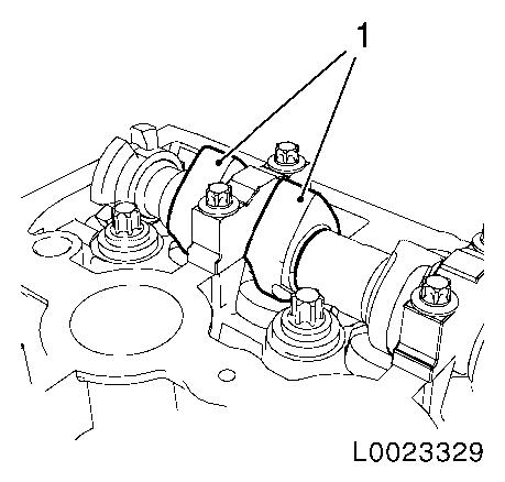
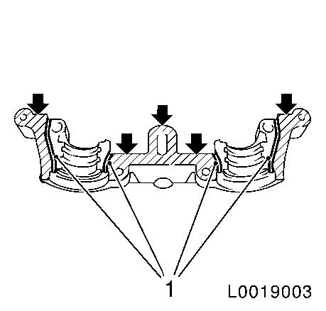
| 49. |
Apply surface sealant to sealing surfaces (arrows) of the
camshaft bearing support thinly and evenly
Note: The grooves (1)
adjacent to the sealing surfaces must remain free from sealant.
|
|
|
| 50. |
Place the camshaft bearing support on the cylinder head and
hand-tighten the bolts (approx. 2 Nm
)
|
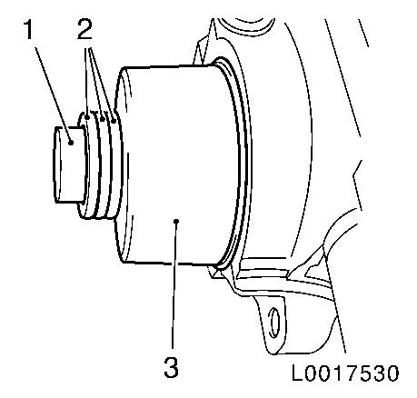
| 51. |
Install 2x camshaft seal ring
| • |
Attach seal ring with KM-422 (3)
until it lies on the cylinder head
| – |
To install, use camshaft sprocket bolt (1) in conjunction with
shims (2) with a total thickness of approx. 10 mm
|
|
|
|
|
Important: No sealant may reach
the camshafts
|
| 52. |
Tighten the camshaft bearing support
| • |
Tighten 4x bolt 8 Nm
| – |
Note installation sequence 1-4
|
|
|
|
|
| 53. |
Install camshaft sensor of exhaust camshaft
| • |
Clip on wiring harness of mixture regulator oxygen sensor to
bracket
|
| • |
Fix wiring harness plug
|
|
| 54. |
Install camshaft sensor, intake camshaft
| • |
Fix wiring harness plug
|
|
| 55. |
Rotate the crankshaft about 60° to TDC of cylinder 1
Note: In direction of
engine rotation.
|
| 56. |
Install rear toothed belt cover
|
|
