|
Cylinder Head, Remove and Install
Note: Only remove
cylinder head with the engine cold
 Remove Remove
| 2. |
Disconnect earth cable from battery
|
| 3. |
Remove air cleaner housing
| • |
Disconnect mass air flow sensor wiring harness plug (2)
|
| • |
Unclip tank vent line (3)
|
| • |
Detach engine vent hose (4) from air intake hose
|
| • |
Detach air intake hose (5) from throttle valve body
|
| • |
Detach air cleaner housing
| – |
Unclip rubber mounting at the bottom
|
| – |
Remove air intake pipe (6)
|
|
|
|

|
| 4. |
Disconnect wiring harness plug, throttle valve module (2)
|
| 5. |
Detach coolant hoses (1) from throttle valve module
| • |
Place collecting pan underneath.
|
|
| 6. |
Unclip coolant hose (3)
|
|
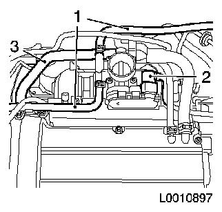
|
| 7. |
Release fuel pressure with KM-J-34730-91 (2) via test connection
| • |
Unscrew protective cap from test connection (1)
|
| • |
Collect escaping fuel in a suitable container
|
| • |
Comply with safety regulations and national legislation
|
|
|
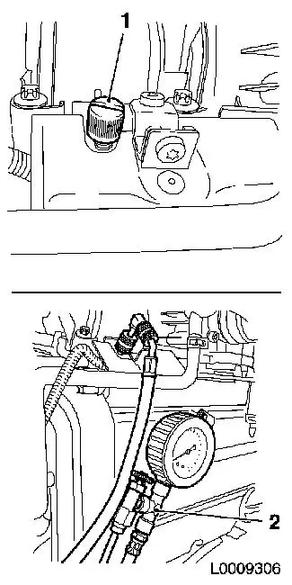
|
| 8. |
Detach fuel supply line (2) with KM-796 (1) from fuel distributor pipe
| • |
Disconnect quick-release fitting
|
|
| 9. |
Detach brake servo vacuum line (3) from intake manifold
| • |
Disconnect quick-release fitting
|
|
|
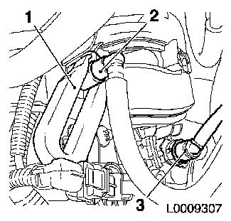
|
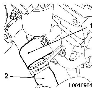
| 10. |
Detach tank vent valve line (1) from intake manifold
|
|
|
| 11. |
Disconnect tank vent valve wiring harness plug (1)
|
|

|
| 12. |
Detach front exhaust pipe (2) from catalytic converter
|
|
|
| 13. |
Drain coolant
| • |
Place collecting pan underneath.
|
| • |
Attach suitable hose to drain connection (2)
|
| • |
Open coolant drain screw (1)
|
| • |
Close coolant drain screw
|
|
|
|
| 14. |
Disconnect wiring harness plugs (1), engine control unit
|
| 15. |
Detach 2x earth cable (4)
|
| 16. |
Disconnect 6x wiring harness plug, engine wiring harness
| • |
Multi-plug (3), ignition module (5), oil pressure switch (6),
coolant temperature sensor (7), camshaft sensor (8)
|
|
|
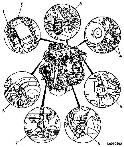
|
| 17. |
Remove thermostat housing (2) from coolant pump
|
| 18. |
Detach coolant hose (1) from radiator
|
|
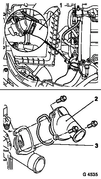
|
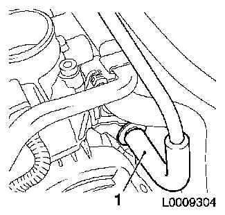
| 19. |
Detach coolant hose (2) from EGR-valve (1)
|
|
|
| 20. |
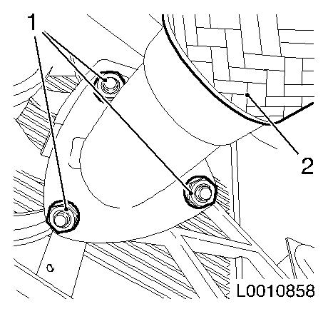
Remove exhaust manifold (up to MY 2005.5) 
|
| 21. |
Remove exhaust manifold (from MY 2005.5)
|
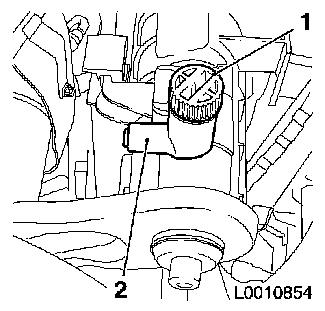
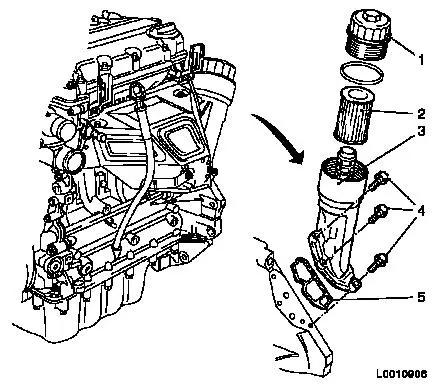
| 22. |
Remove oil filter
| • |
Detach cover (1) from oil filter housing
|
| • |
Remove oil filter insert (2)
|
|
| 23. |
Detach oil filter housing (3) from cylinder block
|
|
|
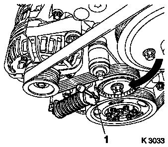
| 24. |
Remove ribbed V-belt
| • |
Mark direction of rotation
|
| • |
Apply tension to ribbed V-belt tensioner (arrow) clockwise with
KM-6131
|
| • |
Relieve tension on ribbed V-belt tensioner
|
|
|
|
| 25. |
Detach coolant pump belt pulley (1) from coolant pump
|
|
|
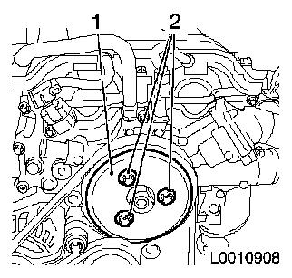
| 26. |
Slacken timing case
| • |
Unscrew 4x bolts, coolant pump (1)
|
| • |
Unscrew 5x bolts, timing case (2) and (3)
|
|
| 27. |
Remove camshaft sensor (5) from timing case
|
|
|
| 28. |
Remove engine vent hose (2) from cylinder head cover
|
| 29. |
Remove ignition module
| • |
Disconnect cooling module wiring harness plug (4)
|
| • |
Pull the cover of the ignition module (1) away from the
cylinder head cover in the direction of the arrow
|
| • |
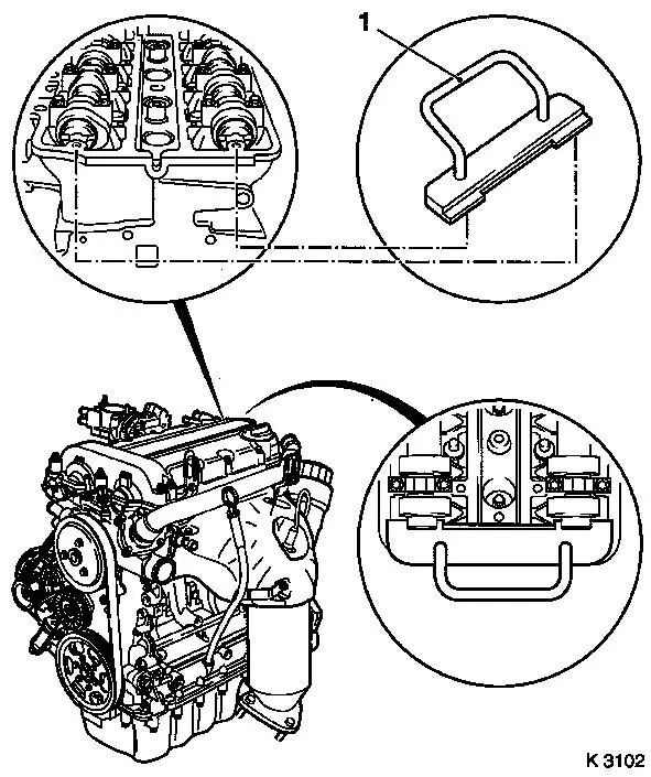
Remove ignition module (5) from spark plugs with KM-6009 (3)
Note: Do not tilt
|
|
| 30. |
Detach cylinder head cover (7) from cylinder head
|
|
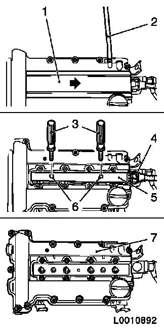
|
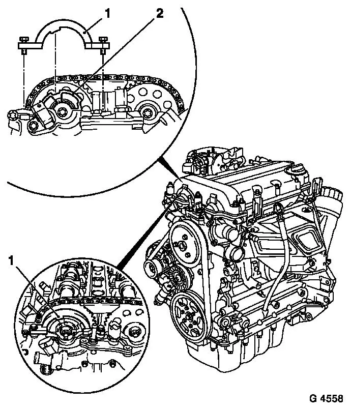
| 31. |
Remove locking screw cylinder block base plate (1)
|
| 33. |
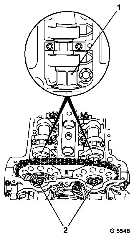
Adjust TDC of combustion stroke of cylinder 1
| • |
Insert KM-952 (2)
| – |
Turn crankshaft evenly until KM-952
engages
|
| – |
Marking on the crankshaft belt pulley (4) must align with the
cast projection (3) on the timing case
|
|
|
|
|
| 34. |
Detach sliding rail (1) from cylinder head
|
| 35. |
Detach camshaft sprockets
| • |
Unscrew 2x bolts (2)
| – |
Counterhold with open-ended wrench against the hexagon (3) of
the camshafts
|
|
| • |
Set aside camshaft sprockets with chain in timing case
|
|
|
|
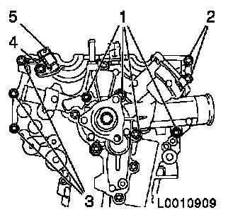
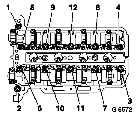
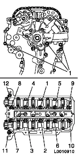
| 36. |
Remove cylinder head bolts
Note: Undo cylinder
head bolts in the order shown
|
|
|
| 37. |
Remove cylinder head
Note: Use a second
person
| • |
Draw chain tensioner past the tension rail
|
| • |
Place cylinder head on wooden blocks
|
| • |
Remove cylinder head gasket
|
|
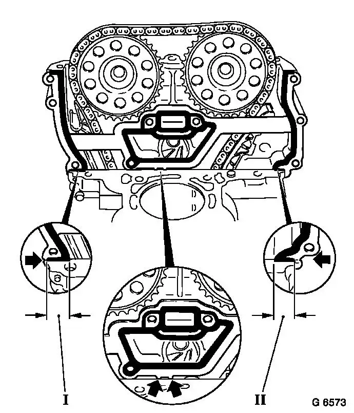
| 38. |
Cut away timing case gasket
| • |
Cut through elastomer sealing lips (dimension I and II) of the
timing case gasket with a sharp knife from inside to outside so
that they are flush on the cylinder block
|
| • |
Bend and snap gasket carefully at the fracturing points
provided (arrows)
|
|
|
|
| 39. |
Remove gasket remnants and clean sealing surfaces
Note: Ensure that no
residues of the elastomer sealing lips remain at the connection
points between the timing case and cylinder block and no residues
from the gasket drop into the timing case
|
| 40. |
Check cylinder head and cylinder block for flatness
|
| 41. |
If the cylinder head is to be checked or overhauled:
| • |
Detach all the external attaching parts from the cylinder head
|
|
| 42. |
Adjust cylinder head gasket
| • |
Cut away projecting elastomer (dimension I) on the timing
side
|
|
|
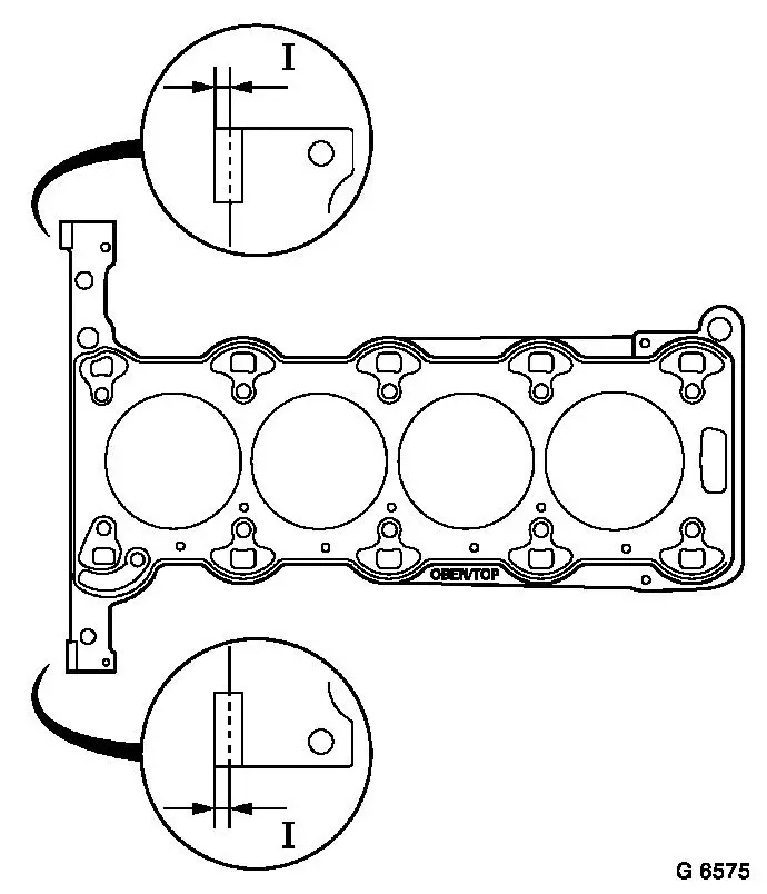
|
 Install
| 43. |
Cylinder Head Gasket, Replace
Note: After applying
the silicone sealing compound, the cylinder head must be brought
into position within 10 minutes and the cylinder head bolts and the
timing case bolt must be screwed in loosely.
| • |
Apply a bead of silicone sealing compound approx. 2 mm thick in
the corner between the timing case/cylinder block
|
| • |
Place new cylinder head gasket on cylinder block
| – |
With TOP/OBEN marking at the top
|
| – |
Press on in the area of the silicone sealing compound
|
|
|
|
|
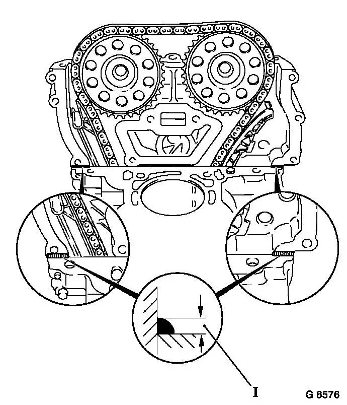
| 44. |
Adjust timing case gasket to fit at the top (1)
| • |
Insert 2x bolt, timing case (arrows)
|
| • |
Position new part gasket (1) on timing case
|
| • |
Press on in the area of the silicone sealing compound
|
| • |
Apply a bead of silicone sealing compound in the corner between
the timing case/cylinder head gasket
| – |
Approx. 2 mm thick (dimension I)
|
|
|
|
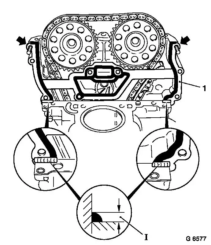
|
| 45. |
Position cylinder head
Note: Use a second
person
| • |
Guide KM-955-1 through opening in
timing case
|
| • |
Draw chain tensioner past the tension rail
|
| • |
Insert pin in guide rail
|
|
| 46. |
Fasten cylinder head
| • |
Screw in new cylinder head bolts a few thread starts
|
| • |
Attach timing case.
Note: Position cylinder
head in the direction of the timing case by striking it gently with
a rubber mallet
| – |
Tighten 3x bolt (1) 8 Nm
|
|
| • |
Tighten 12x cylinder head bolt 25 Nm +
60° + 60° + 60°
| – |
Note correct tightening sequence
|
|
|
|
|
| 48. |
Fasten timing case
| • |
Release lower 3 bolts (screws fitted beforehand) from cylinder
head again
|
| • |
Install coolant pump bolts
| – |
Tighten 4x bolt (1) 8 Nm
|
|
| • |
Install timing case bolts
| – |
Tighten 5x bolt (2) and (3) 8 Nm
|
|
| • |
Attach camshaft sensor (5) with new seal ring
|
|
|
|
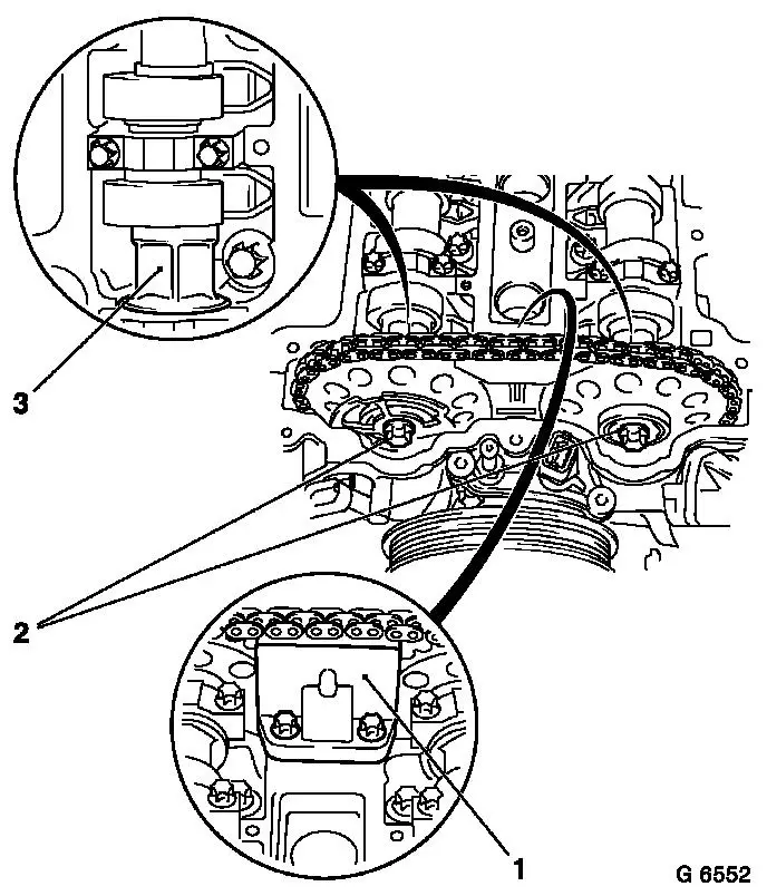
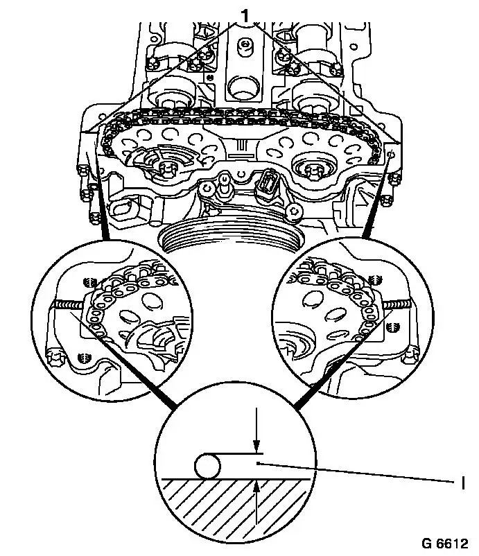
| 49. |
Turn camshafts by the hexagon (short distance) until KM-953 (1) can be inserted in the grooves of
the camshafts
Note: Turn camshafts
carefully and evenly
|
| 50. |
KM-953 must engage as far as the stop
in the grooves of the camshafts
|
|
|
| 51. |
Attach camshaft sprockets
| • |
Position camshaft sprockets on camshafts with timing chain
|
| • |
Hold phase sensor disc on camshaft, intake side
|
| • |
Tighten 2x bolt, camshaft sprockets, hand-tight
| – |
It must still be possible to turn the phase sensor disc on the
intake camshaft by hand
|
|
|
| 52. |
Attach sliding rail to cylinder head
|
| 53. |
Attach KM-954 to timing case
| • |
Turn phase sensor disc (2) in such a way that KM-954 (1) can be inserted on the timing case
|
|
|
|
| 55. |
Fasten camshaft sprockets
Note: Tightening torque
10 Nm serves to fix the camshaft
sprockets and the phase sensor disc temporarily
| • |
Tighten 2x bolt (2) 10 Nm
Note: First of all
tighten bolt of intake camshaft sprocket
| – |
Counterhold the camshafts on the hexagon (1)
|
|
|
|
|
| 56. |
Remove locking tools KM-954 , KM-953 and KM-952
Note: Locking tools may
not be used for counterholding
|
| 57. |
Tighten camshaft sprockets
Note: Use a second
person
| • |
Tighten 2x bolt 50 Nm + 60°
|
|
| 58. |
Timing, Check
| • |
Turn crankshaft through 720°
|
| • |
Insert KM-953 into camshafts
|
| • |
Attach KM-954 on phase sensor
disc
Note: if KM-954 cannot be inserted, the operation "Timing,
Adjust" must be repeated
|
|
| 59. |
Remove KM-954 , KM-953 and KM-952
|
| 60. |
Attach chain tensioner closure bolt to timing case 50 Nm
|
| 61. |
Attach closure bolt with new seal ring to cylinder block base
plate 60 Nm
|
| 62. |
Apply sealing compound
| • |
Disconnect projecting part of timing case gasket (1) flush with
cylinder head/timing case
|
| • |
Apply a bead of silicone sealing compound approx. 2 mm thick
(dimension I)
Note: The cylinder head
cover must be fitted within 10 minutes of applying the silicone
sealing compound
|
|
|
|
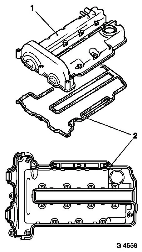
| 63. |
Attach cylinder head cover
| • |
Insert new gasket (2) in cylinder head cover (1)
|
| • |
Tighten 13x bolt 8 Nm
Note: Bolts must be
checked visually to check whether the elastomer seal is damaged. If
the elastomer seal is damaged, the bolt must be replaced with a new
one.
|
|
|
|
| 64. |
Install ignition module
| • |
Connect ignition module to spark plugs
|
| • |
Attach ignition module cover to cylinder head cover
|
| • |
Fix wiring harness plug
|
|
| 65. |
Attach engine vent hose to cylinder head cover
|
| 66. |
Attach coolant hose to coolant pump
|
| 67. |
Insert ribbed V-belt
| • |
Position ribbed V-belt
| – |
Ensure correct running direction and installation position
|
|
| • |
Apply tension to ribbed V-belt tensioner with KM-6131
|
| • |
Relieve tension on ribbed V-belt tensioner
|
|
| 68. |
Attach oil filter housing to cylinder block
|
| 69. |
Install oil filter
| • |
Push new seal ring on to oil filter housing cover
|
| • |
Attach oil filter housing cover with new oil filter insert to
oil filter housing 25 Nm
|
|
| 70. |
Install exhaust manifold (up to MY 2005.5)
|
| 71. |
Install exhaust manifold (from MY 2005.5)
|
| 72. |
Attach coolant hoses to throttle valve body
|
| 73. |
Attach coolant hose to EGR-valve
|
| 74. |
Attach thermostat housing to coolant pump
|
| 75. |
Attach upper radiator hose to radiator
|
| 76. |
Attach engine management wiring harness
| • |
Connect engine management wiring harness
| – |
Connect 14x wiring harness plugs
|
| – |
Screw in 3x earth cable
|
|
|
| 77. |
Attach front exhaust pipe to exhaust manifold with new gasket
and new nuts
|
| 78. |
Attach tank vent valve to bracket
|
| 79. |
Attach brake servo vacuum hose to intake manifold
|
| 80. |
Attach tank vent valve line to intake manifold
|
| 81. |
Attach fuel supply line to fuel rail
|
| 82. |
Connect wiring harness plug, throttle valve module
|
| 83. |
Install air cleaner housing
| • |
Connect air intake hose
|
| • |
Attach engine vent hose
|
| • |
Connect 2x wiring harness plugs
| – |
Hot film air mass flow meter, tank vent valve
|
|
|
| 84. |
Connect wiring harness plug, tank vent valve
|
| 85. |
Connect earth cable to battery
|
| 86. |
Fill and bleed cooling system
|
| 87. |
Check engine oil level, correct if necessary
|
| 88. |
Program volatile memories
|
|
