|
Cylinder Head, Remove and Install (Z16XE1)
 Remove Remove
| 2. |
Remove intake manifold
|
| 3. |
Remove exhaust manifold
|
| 4. |
Detach lower engine compartment cover / splashguard
|
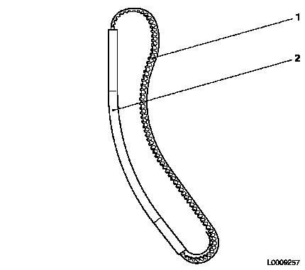
| 5. |
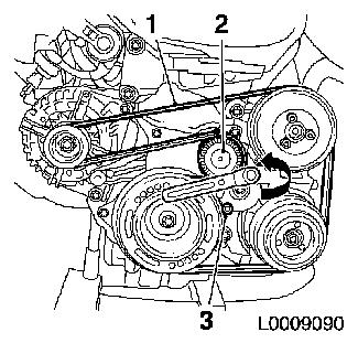
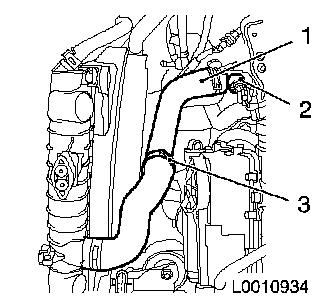
Detach ribbed V-belt (1)
| • |
Mark direction of rotation
|
| • |
Apply tension to ribbed V-belt tensioner (2) in the direction
of the arrow and fix with KM-6130 (3)
|
|
|
|
| 6. |
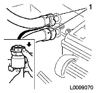
Disconnect coolant hoses from heater core
| • |
Pull off 2x coolant hoses (1)
| – |
Detach in direction of arrow
|
|
|
|
|
| 7. |
Disconnect camshaft sensor wiring harness plug
|
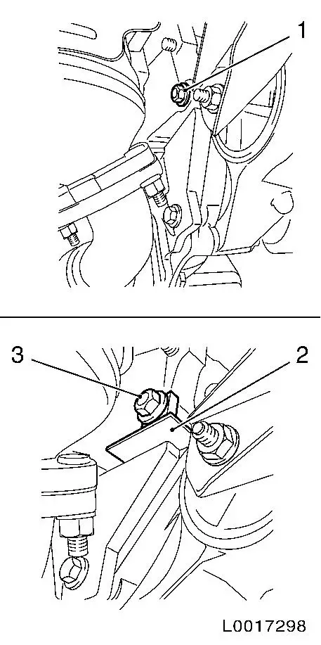
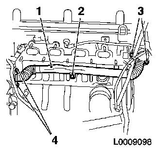
| 8. |
Disconnect thermostat wiring harness plug (1)
|
| 9. |
Disconnect wiring harness plug for coolant temperature sensor
(3)
|
| 10. |
Disconnect wiring harness plug of EGR valve (4)
|
|

|
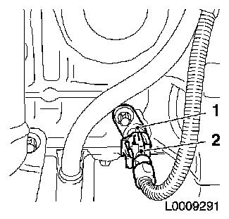
| 11. |
Disconnect wiring harness plug (2) of crankshaft pulse pick-up
(1)
|
|
|
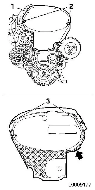
| 12. |
Detach front toothed belt cover (top) (1)
| • |
Release upper catch (3)
|
| • |
Pull front toothed belt cover (top) upwards by cast projection
(arrow), applying slight tension
|
|
|
|
| 13. |
Raise vehicle by its full height
|
| 14. |
Block crankshaft.
| • |
Attach KM-6625
| – |
Detach screwed connection (1)
|
| – |
Tighten screwed connection (3)
|
|
|
|
|
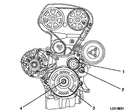
| 15. |
Detach torsional vibration damper (3)
|
| 16. |
Detach ribbed V-belt tensioner (1)
| • |
Unscrew bolt (2)
| – |
Ribbed V-belt tensioner remains locked with KM-6130
|
|
|
|
|
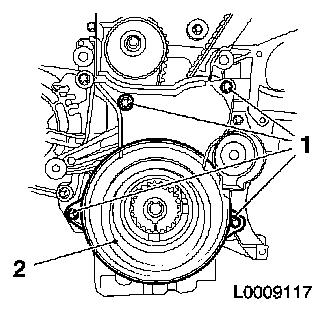
| 17. |
Detach front toothed belt cover (bottom) (2)
|
|
|
| 18. |
Set engine to TDC
| • |
Screw in bolt, torsional vibration damper
|
| • |
Move crankshaft in direction of engine rotation to "cylinder 1
TDC of combustion stroke" (III)
|
|
| 19. |
Lower vehicle by its full height
|
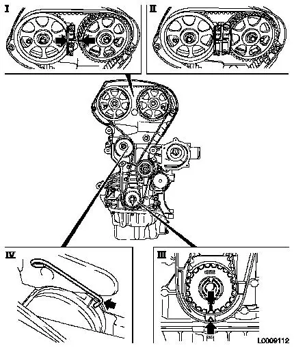
| 20. |
Lock camshaft sprockets in position with KM-6340
| • |
Position camshaft sprockets in such a way that the markings
(arrows) are opposite each other
|
| • |
Attach KM-6340-Left to intake
camshaft sprocket (I)
|
|
| 21. |
Remove toothed belt
| • |
Mark direction of rotation
|
| • |
Apply tension to toothed belt tension roller clockwise, using
an Allen key and fix using KM-6333
(IV)
|
|
|
|
| 22. |
Detach lower coolant hose (1) from thermostat housing (2)
|
|
|
| 23. |
Remove coolant pipe (1)
| • |
Unscrew 5x bolts (2), (3) and (4)
|
|
|
|
| 24. |
Remove cylinder head cover
|
Important: Remove cylinder head
only when engine is cold (room temperature)
|
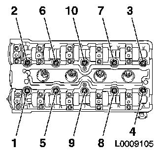
| 25. |
Remove cylinder head
| • |
Unscrew 10x bolt
Note: Unfasten bolts in
the order shown
|
|
|
|
| 26. |
Remove cylinder head
Note: Second
mechanic
| • |
Lay cylinder head on suitable base
|
| • |
Remove cylinder head gasket
|
|
| 27. |
Clean sealing surfaces.
|
| 28. |
Cylinder Head, Check for Plane Surface 
|
 Install
| 29. |
Position cylinder head
Note: Second
mechanic
| • |
Install cylinder head gasket
|
Important: Check installation
position
|
| • |
Position cylinder head
|
|
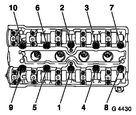
| 30. |
Install cylinder head
| • |
Tighten 10x bolt 25 Nm + 90° +
90° + 90° + 45°
Note: Note correct
tightening sequence
| – |
Use new cylinder head bolts
|
|
|
|
|
| 31. |
Install cylinder head cover
|
| 33. |
Install exhaust manifold
|
| 34. |
Install intake manifold
|
| 35. |
Insert toothed belt
Note: Threading the
toothed belt through the engine damping block support is only
permissible in conjunction with the assembly tool supplied with new
toothed belts as otherwise it is possible to damage the toothed
belt at this stage by kinking it
| • |
Insert toothed belt (1) in enclosed assembly tool (2)
| – |
If the toothed belt has been used, observe direction of
rotation
|
|
| • |
Guide toothed belt through engine damping block support with
assembly tool
|
|
|
|
| 36. |
Position toothed belt
Note: If the toothed
belt has been used, observe direction of rotation
| • |
Place toothed belt on exhaust camshaft sprocket
|
| • |
Place toothed belt on intake camshaft sprocket
|
| • |
Guide toothed belt past the tensioning and guide rollers and
place on toothed belt drive gear
|
| • |
Apply tension to the toothed belt tension roller and remove
KM-6333
|
|
| 39. |
Turn crankshaft through 720°
| • |
2 revolutions in direction of engine rotation
|
| • |
Place toothed belt drive gear on the marking, cylinder 1 TDC of
combustion stroke
|
|
| 41. |
Lock camshaft sprockets in position with KM-6340
| • |
Insert KM-6340-Right
Note: Markings on
camshaft sprockets must align - otherwise dismantle toothed belt
and place in position again
|
|
| 44. |
Attach front toothed belt cover (bottom)
|
| 45. |
Remove bolt on torsional vibration damper
| • |
Block flywheel using KM-6625
|
|
| 46. |
Fit torsional vibration damper
Important: Use new bolt
|
| • |
Tighten bolt 95 Nm + 45° +
15°
|
|
| 47. |
Remove KM-6625
| • |
Detach screwed connection
|
| • |
Tighten bolted connection
|
|
| 48. |
Attach ribbed V-belt tensioner
|
| 49. |
Insert ribbed V-belt
Note: Observe direction
of rotation
| • |
Apply tension to ribbed V-belt tensioner anti-clockwise and
place ribbed V-belt in position
|
|
| 50. |
Attach lower engine compartment cover / splashguard
|
Important: Ensure that it is
latched correctly
|
| 51. |
Attach front toothed belt cover (top)
|
Important: It is imperative to
adhere to the following assembly order
|
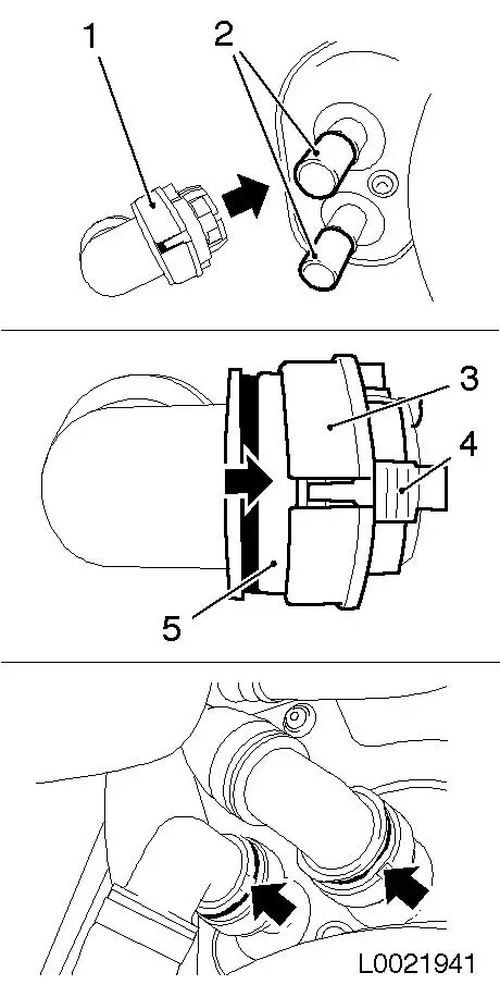
| 52. |
Attach cooling hoses to heater core
| • |
Fit 2x quick release fittings (1) onto heater core connection
port (2) as far as they will go
Note: Pay attention to
coloured markings
|
| • |
Slide the 2x quick-release fitting catches (3) in the direction
of the arrow all the way to the stop by simultaneously pressing the
release buttons (4)
| – |
The colour rings (5) must be visible
|
|
| • |
Check that quick release fittings are correctly seated and that
the colour rings (5) are visible
|
|
|
|
| 53. |
Attach lower coolant hose to thermostat housing
|
| 54. |
Top up coolant, correct if necessary
|
| 55. |
Program volatile memories
|
|
