|
Replace all valve stem seals (cylinder head
installed)
 Remove Remove
| 2. |
Remove spark plugs with KM-194-E
|
| 4. |
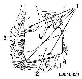
Remove right engine splash guard (2)
| • |
Remove 2x body-bound rivets (3)
|
|
|
|
| 5. |
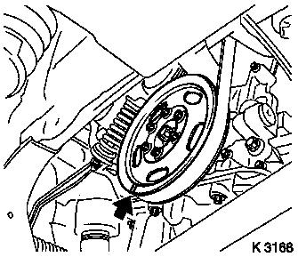
Make alignment mark
| • |
on crankshaft belt pulley (arrow)
Note: 180° offset
to marking TDC of combustion stroke cylinder 1
|
|
|
|
| 6. |
Prepare automatic valve spring lever MKM-6086
| • |
Adjust MKM-6086-6 supports (2)
| – |
Adjust support heads (1) so that they are centred in respect of
the support feet (2) and tighten
|
|
| • |
Complete lever arm MKM-6086-7
| – |
with joint MKM-6086-8 and dismantling
head MKM-6086-10
|
|
|
| 7. |
Complete assembly set MKM-6086-200
| • |
Insert thrust piece MKM-6086-200-10
(3)
Note: Note
manufacturer's provisions
|
|
|
|
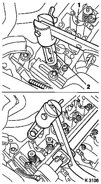
| 8. |
Attach automatic valve spring lever MKM-6086
| • |
Attach supports ( MKM-6086-6 1)
| – |
Push assembly shaft in the supports
Note: Align assembly
shaft centrally via spark plug bore
|
|
| • |
Install lever arm MKM-6086-7 (2)
Note: Removal head must
point towards the intake side
|
| • |
Secure installation shaft
|
|
| 9. |
Install compressed air adapter
| • |
Screw into spark plug thread of cylinder 1
|
| • |
Apply compressed air to cylinder 1
|
|
|
|
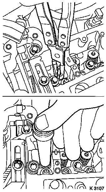
| 10. |
Remove intake valve springs, cylinder 1
| • |
Press valve spring carefully downwards with lever arm (1)
Note: Removal head (2)
must be positioned vertically over the valve stem
|
Important: Observe correct
assignment
|
| • |
Take out valve cotters, valve discs, valve springs
Note: Do not use any
magnetic tools
|
|
|
|
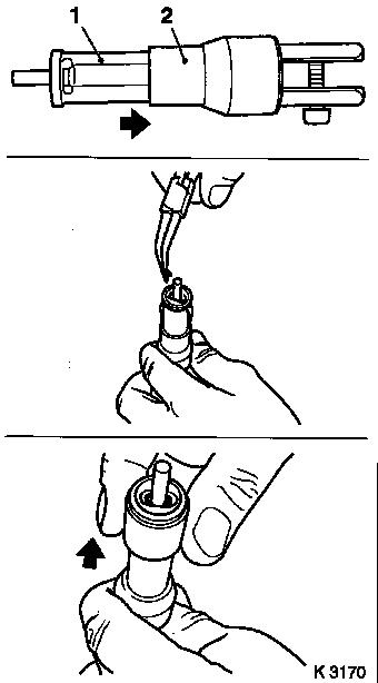
| 11. |
Replace valve stem seals
| • |
Place new valve stem seal on to valve stem
|
| • |
Drive in as far as the stop with KM-958
|
|
|
|
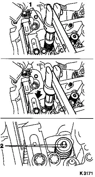
| 12. |
Install intake valve springs, cylinder 1
| • |
Insert valve springs and valve heads
|
| • |
Insert valve cotters into assembly head (1)
| – |
Slide plastic clamping sleeve (2) in direction of lever arm
mount
|
Important: Insert valve cotters
with tapered end towards valve
|
| – |
Insert valve cotters
|
| – |
Push plastic clamping sleeve in the direction of the valve
(arrow)
|
|
|
|
|
| 13. |
Install valve cotters
| • |
Attach assembly head (1) to lever arm
|
Important: Assembly head must
stand vertically above valve stem. Valve cotters (2) must engage
audibly
|
| • |
Press valve spring carefully downwards with lever arm
(arrow)
|
Important: Do not make a 2nd
attempt without checking that both valve cotters are seated in the
assembly head. Check seat of valve cotters. Ensure compressed air
is being applied.
|
| • |
|
|
|
|
| 14. |
Transfer lever arm
| • |
Install lever arm
Note: Removal head must
point towards the exhaust side
|
|
| 15. |
Remove exhaust valve springs, cylinder 1
| • |
Press valve spring carefully downwards with lever arm
Note: Removal head must
be positioned vertically over the valve stem
|
Important: Observe correct
assignment
|
| • |
Take out valve cotters, valve discs, valve springs
Note: Do not use any
magnetic tools
|
|
| 16. |
Replace valve stem seals
| • |
Place new valve stem seal on to valve stem
|
| • |
Drive in as far as the stop with KM-958
|
|
| 17. |
Install exhaust valve springs, cylinder 1
| • |
Insert valve springs and valve heads
|
| • |
Insert valve cotters into assembly head (1)
| – |
Slide plastic clamping sleeve (2) in direction of lever arm
mount
|
Important: Insert valve cotters
with tapered end towards valve
|
| – |
Insert valve cotters
|
| – |
Push plastic clamping sleeve in the direction of the valve
(arrow)
|
|
|
|
|
| 18. |
Install valve cotters
| • |
Attach assembly head to lever arm
|
Important: Assembly head must
stand vertically above valve stem. Valve cotters must engage
audibly
|
| • |
Press valve spring carefully downwards with lever arm
|
Important: Do not make a 2nd
attempt without checking that both valve cotters are seated in the
assembly head. Check seat of valve cotters. Ensure compressed air
is being applied.
|
| • |
|
|
| 19. |
Transfer compressed air adapter
| • |
Interrupt compressed air feed
|
| • |
Unscrew from spark plug thread of cylinder 1
|
| • |
Screw into spark plug thread of cylinder 4
|
| • |
Apply compressed air to cylinder 4
|
|
| 21. |
Replace valve stem seals, cylinder 4
|
| 22. |
Interrupt compressed air feed
|
| 23. |
Remove crankshaft lock KM-952
|
| 24. |
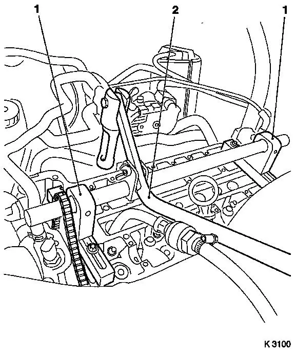
Adjust TDC of combustion stroke of cylinder 3
| • |
Pull timing chain upwards
|
| • |
Turn crankshaft evenly (180°)
Note: Marking made as
aid on crankshaft belt pulley must align with cast projection on
timing case
|
|
| 25. |
Lock crankshaft with KM-952
|
| 26. |
Transfer compressed air adapter
| • |
Interrupt compressed air feed
|
| • |
Unscrew from spark plug thread of cylinder 4
|
| • |
Screw into spark plug thread of cylinder 2
|
| • |
Apply compressed air to cylinder 2
|
|
| 27. |
Replace valve stem seals, cylinder 2
|
| 28. |
Transfer compressed air adapter
| • |
Interrupt compressed air feed
|
| • |
Unscrew from spark plug thread of cylinder 2
|
| • |
Screw into spark plug thread of cylinder 3
|
| • |
Apply compressed air to cylinder 3
|
|
| 29. |
Replace valve stem seals, cylinder 3
|
| 30. |
Interrupt compressed air feed
|
| 31. |
Detach automatic valve spring lever
|
| 32. |
Remove compressed air adapter
|
| 33. |
Slacken crankshaft
| • |
Put transmission into neutral
|
|
| 35. |
Lock crankshaft
| • |
Pull timing chain upwards
|
| • |
Turn crankshaft evenly until KM-952
engages
|
|
 Install
| 37. |
Install spark plugs with KM-194-E
25 Nm
|
| 38. |
Visually check components
| • |
Camshafts, camshaft bearing caps, cylinder head, roller cam
followers, hydraulic valve lifters
|
|
| 39. |
Install hydraulic rams, roller cam followers and camshafts 
|
|
